

UK based
Prices for UK customers are shown inc 20% VAT
Other countries, inc EU, prices shown are ex VAT.


UK based
Prices for UK customers are shown inc 20% VAT
Other countries, inc EU, prices shown are ex VAT.
Please note: you need to do some milling on the metal chassis to fit the new motor.
What you need for conversion set
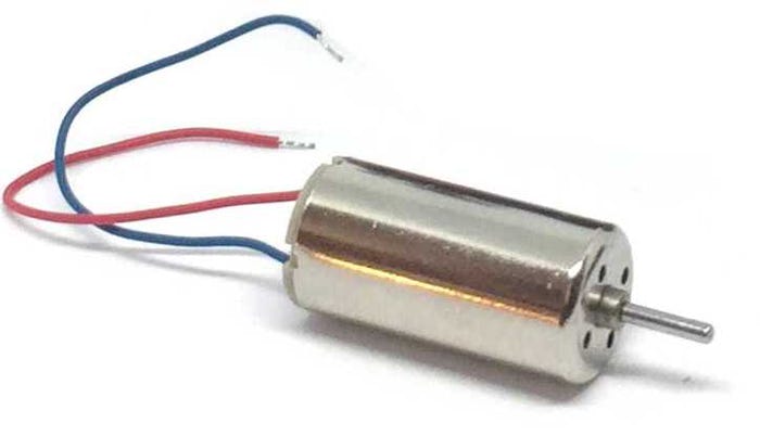
- The model and upgrade motor
- Soldering iron 15W/25W
- Milling drill bit and (bench) drill
- General model making tools
Installation time: Around 60-90 minutes
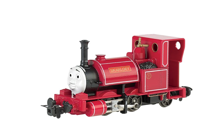
Conversion Bachmann Skarloey
Ultimate Motor Upgrade
Upgraded model
Content of the offer.
Question? Just reach out!
1
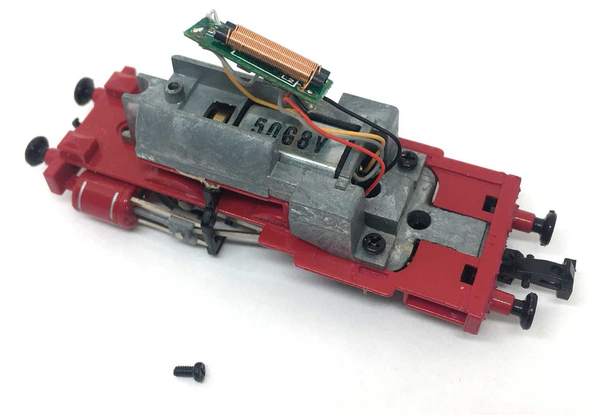
Installation instructions
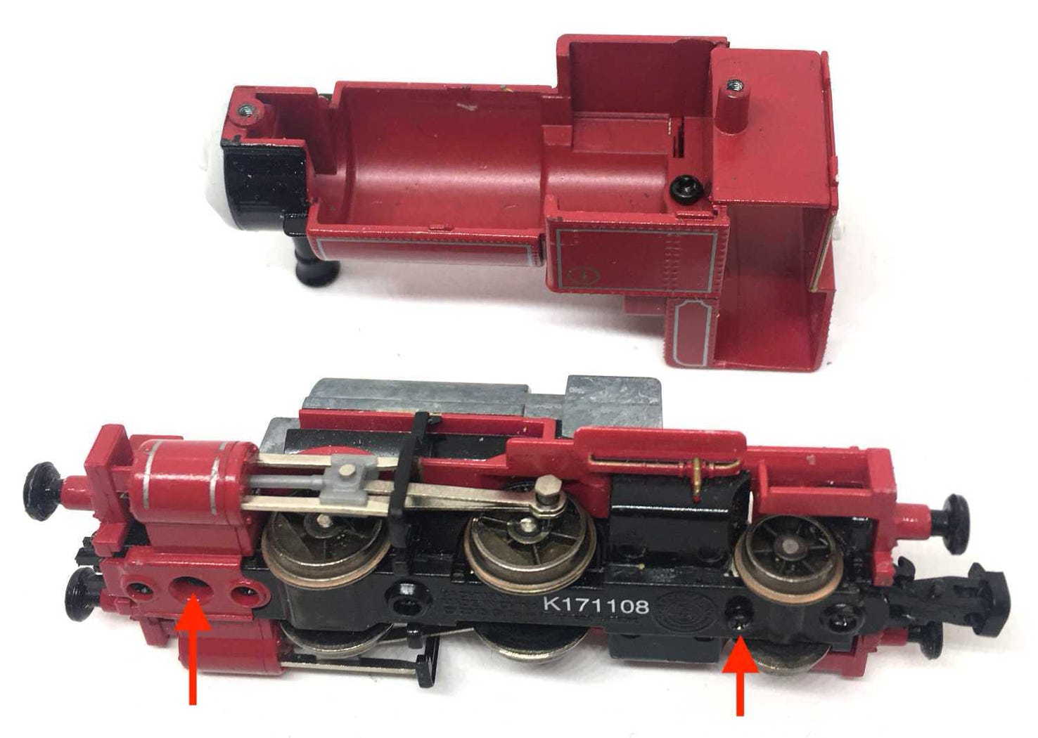
Release the two screws on the bottom.
2
Remove the screw to release the board with the electronics.
3
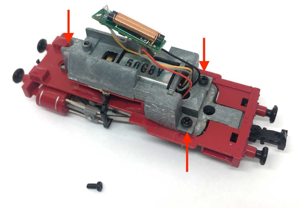
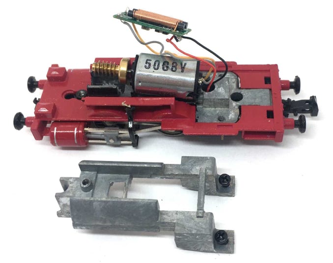
Remove the three screws to release the white metal block and remove the block.
4
5
6
Protect the chassis well when milling, so the metal residue doesn’t get into the gears. It’s very hard to clean if you don’t. I keep a vacuum cleaner next to it, when milling.
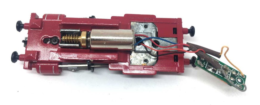
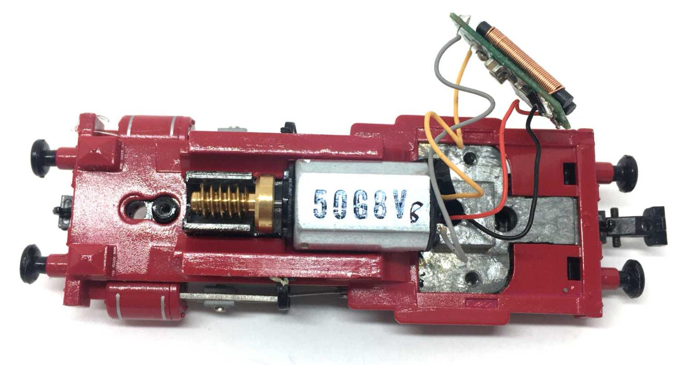
Take the original motor out and de-solder the wires. Then, with care, remove the worm and flywheel.
It’s easy to remove the worm from the motor. Just slide a sharp pair of tweezers through the gap, push the tweezers forward and you slide the worm (and flywheel; they are two separate parts) out. Make a mental note of the positioning of the flywheel. The deeper part has to be in the direction of the worm, when you place it on the new motor.
Push in this direction.
The flywheel and worm can be pushed on by hand. No real force nor adapter is needed. Make sure you push on the rear of the motor and not on the shaft side, as otherwise you press the motor out of the housing.
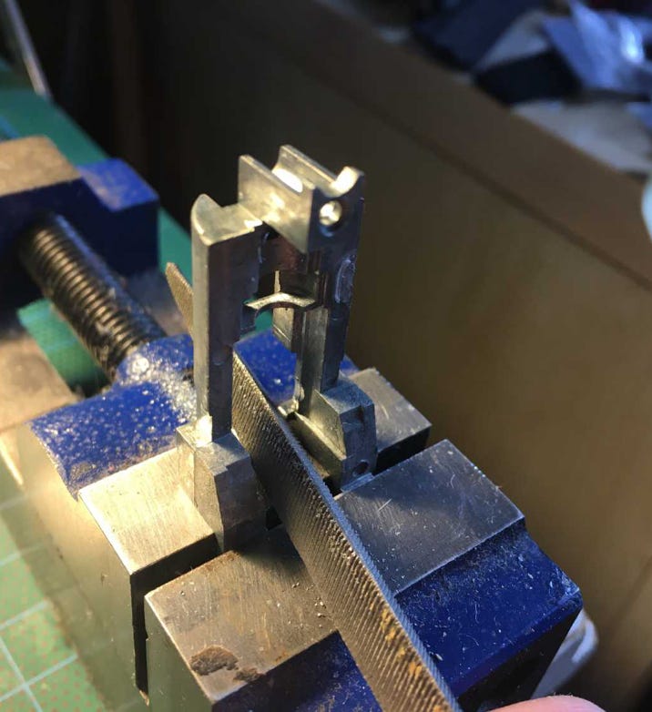
If you have a milling bit and a bench drill, milling in the chassis to make space for the motor should not be hard to do. You only need 0.5 mm more space on the back end. This needs to be taken off the motor chassis, as well as the white metal block. For the metal block, use a rough file.
Here I use a flat file for the metal block. Continue until only a thin piece remains. Check with the motor in the model how far you have to go.
7
8
First, fit the supplied 0.25 mm piece of styrene on the chassis. Glue with superglue. Then glue the motor on top of that, with Epoxy glue. I used Araldite, the version with 90 seconds drying time.
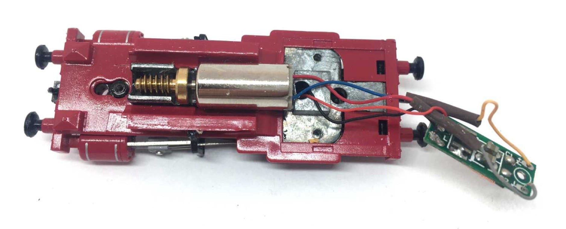
Solder the blue and red wires of the motor directly to the electronics board (above). The blue cable of the motor is the plus, so connect this to the plus on the board (where now the orange cable is. There is a plus sign on the board). So:
Blue to +
Red to -
I measured wrong and cut the motor cables, so that’s why they are connected to the orange and grey wires. But you don’t need to, just connect them directly to the board.
9
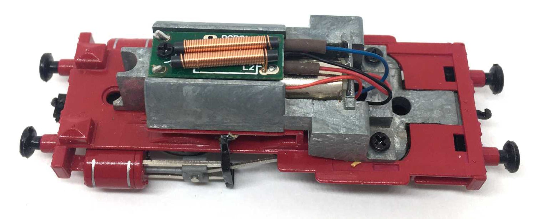
Screw the metal block and electronics board back in place and test the model.
Digital
If it all works well, you can make the model digital by replacing the electronics board with a decoder. You need a decoder that is smaller than 8mm, to fit in place of the current PCB. You can read all about DCC and DCC sound conversion here.
For optimal performance, you need to change some CV settings on a decoder. For several decoder brands, the ideal CV settings can be found by clicking here.
END
•