Prices for UK customers are shown inc 20% VAT
Other countries, inc EU, prices shown are ex VAT.
UK based
KASTENLOK INDEX
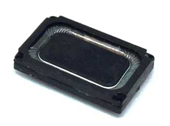
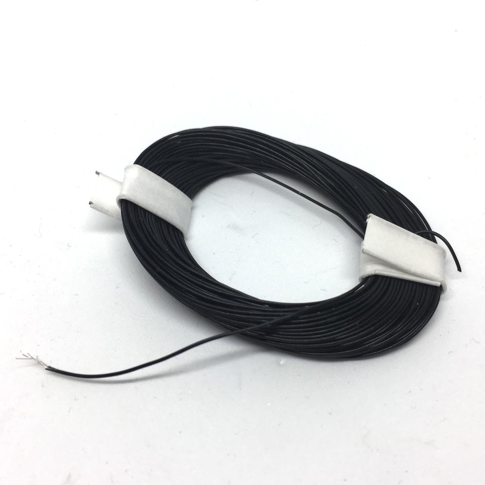
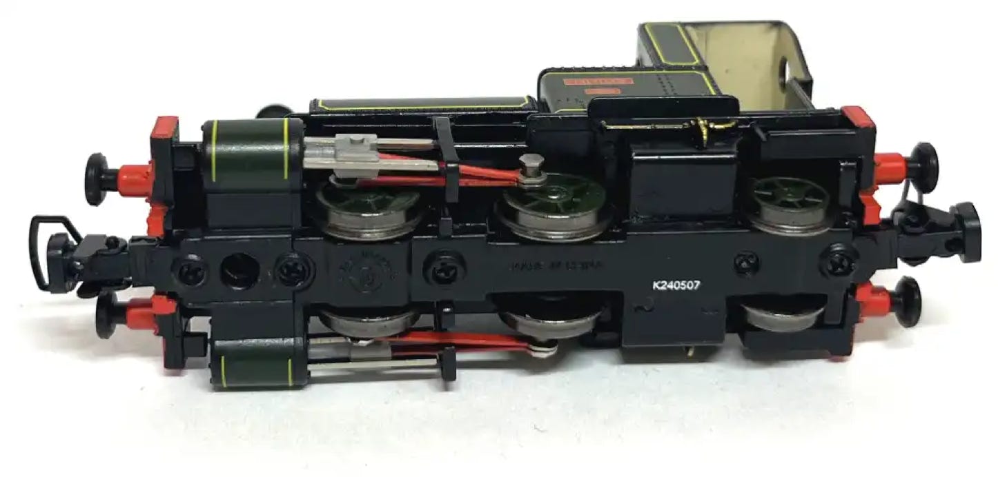
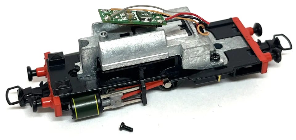
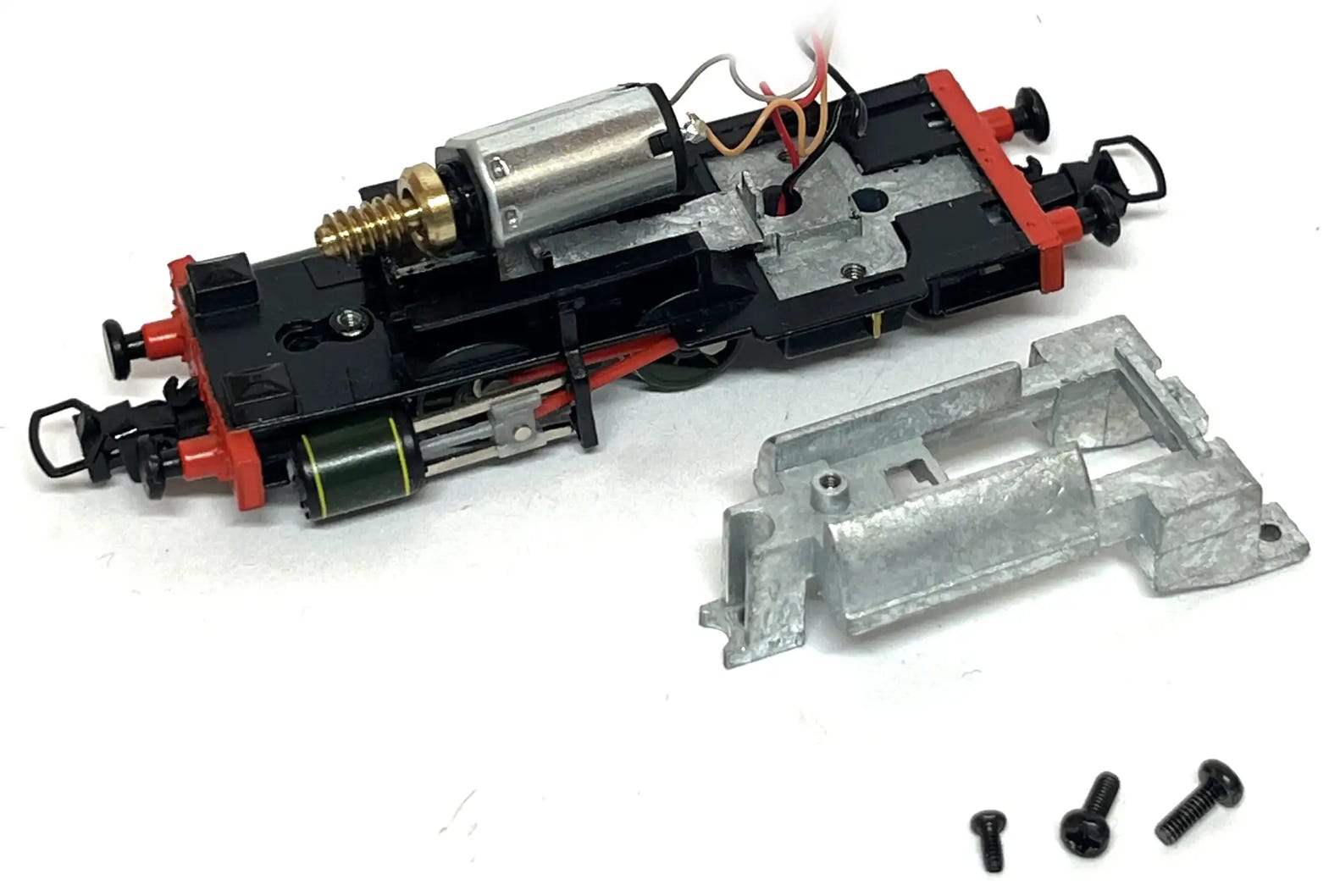
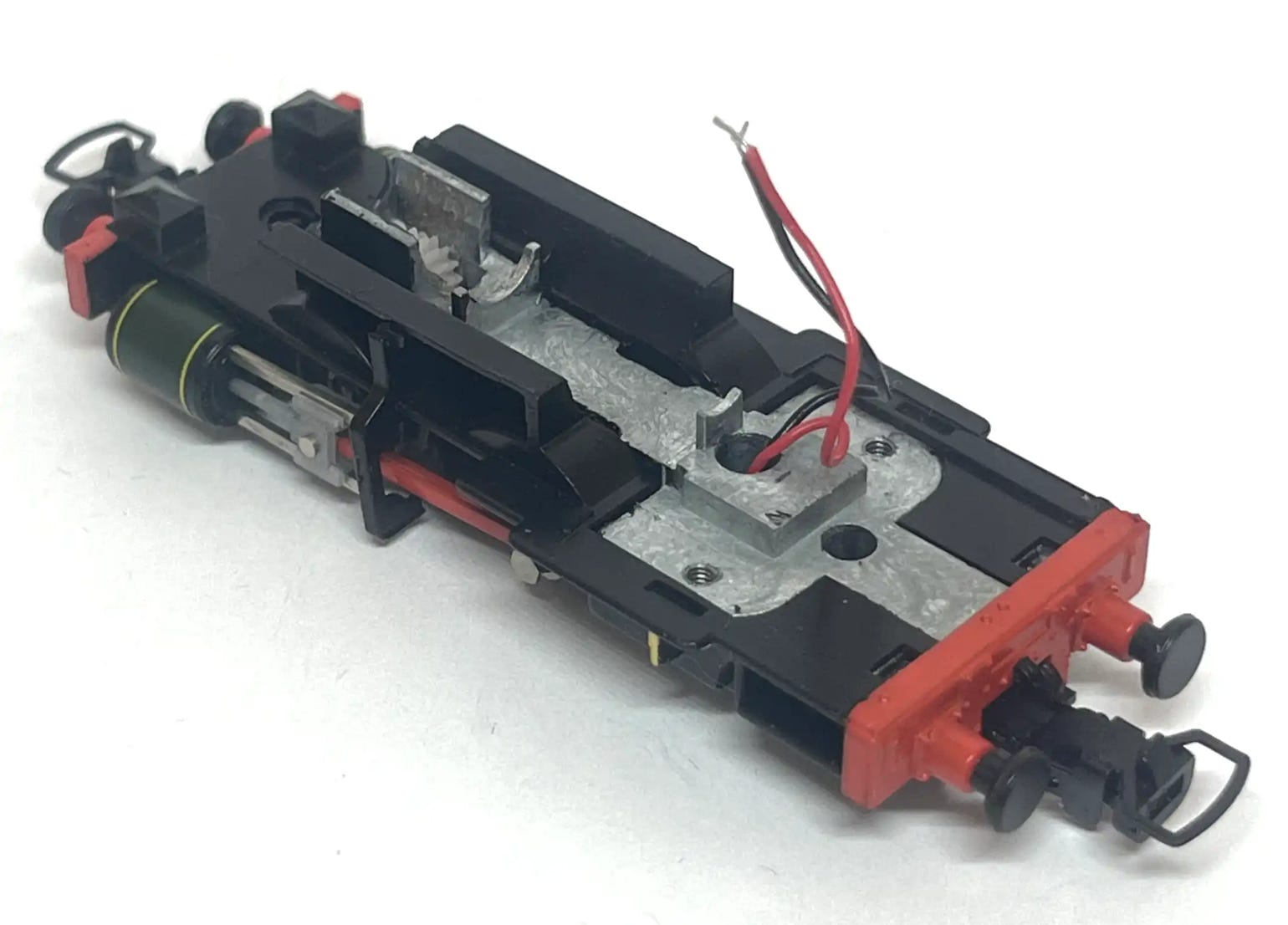
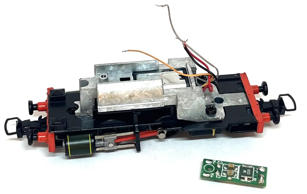
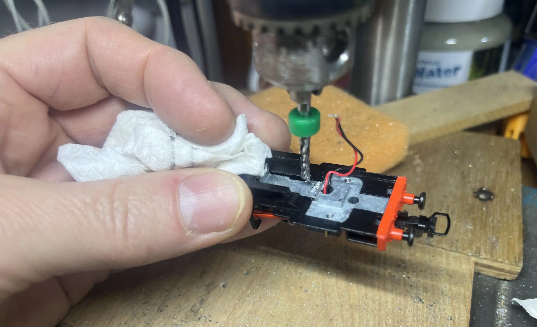
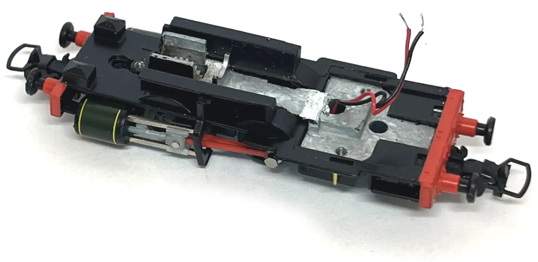
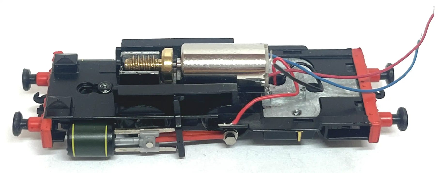
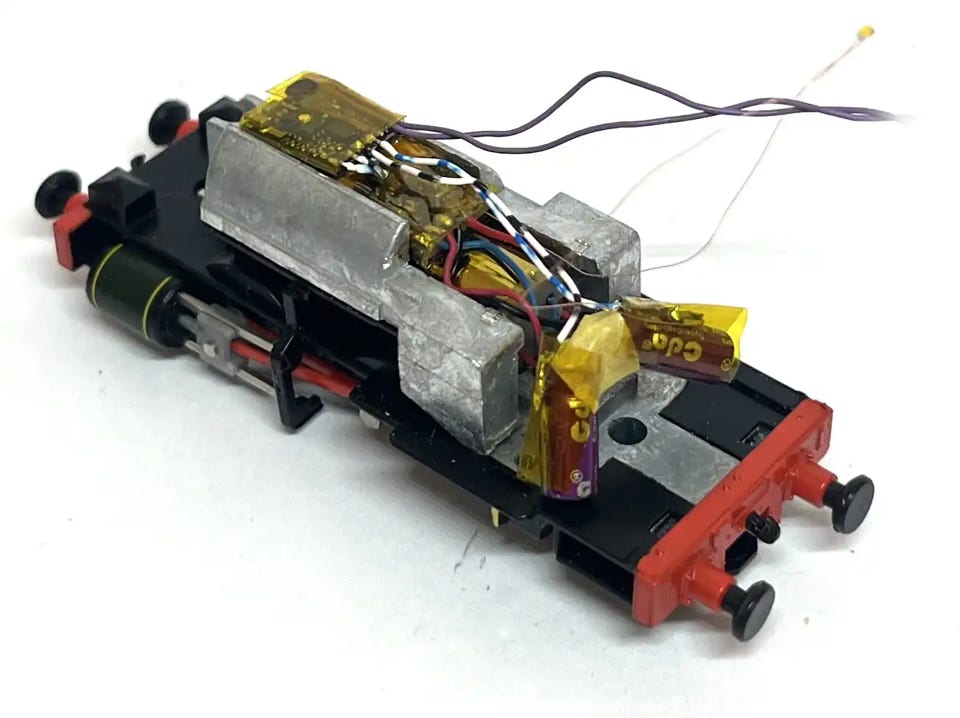
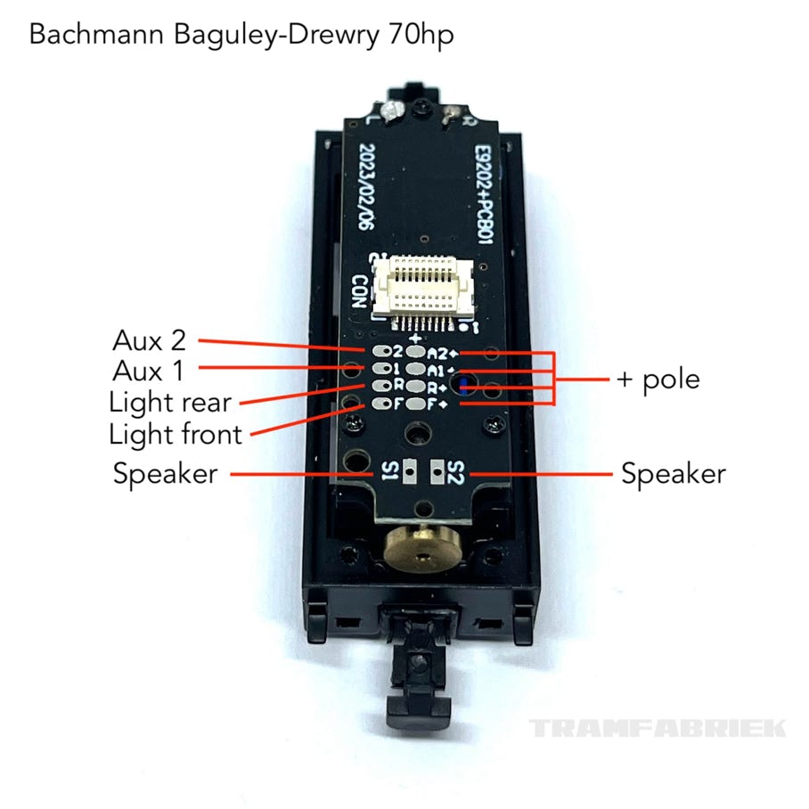
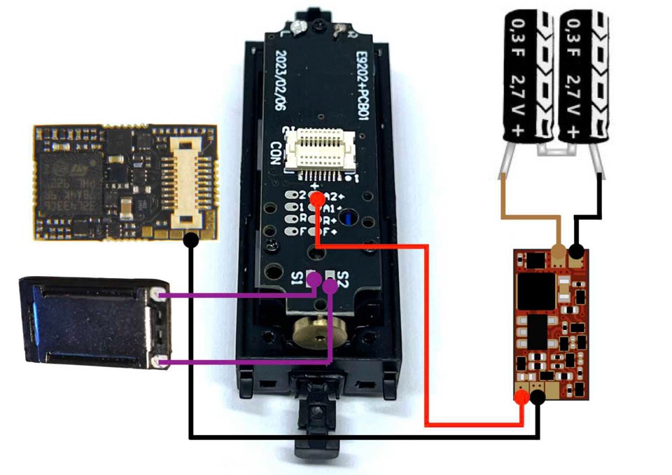
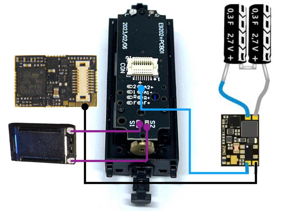
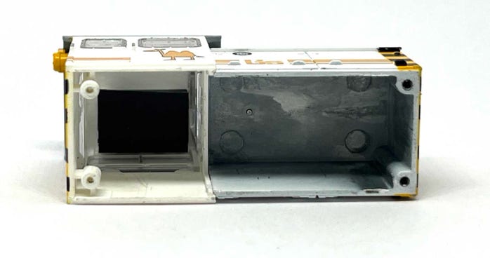
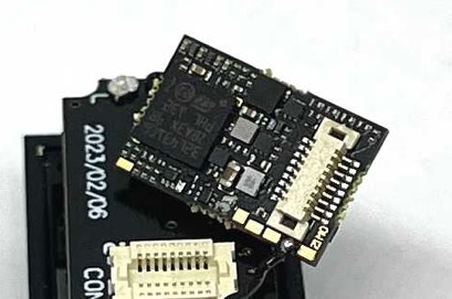
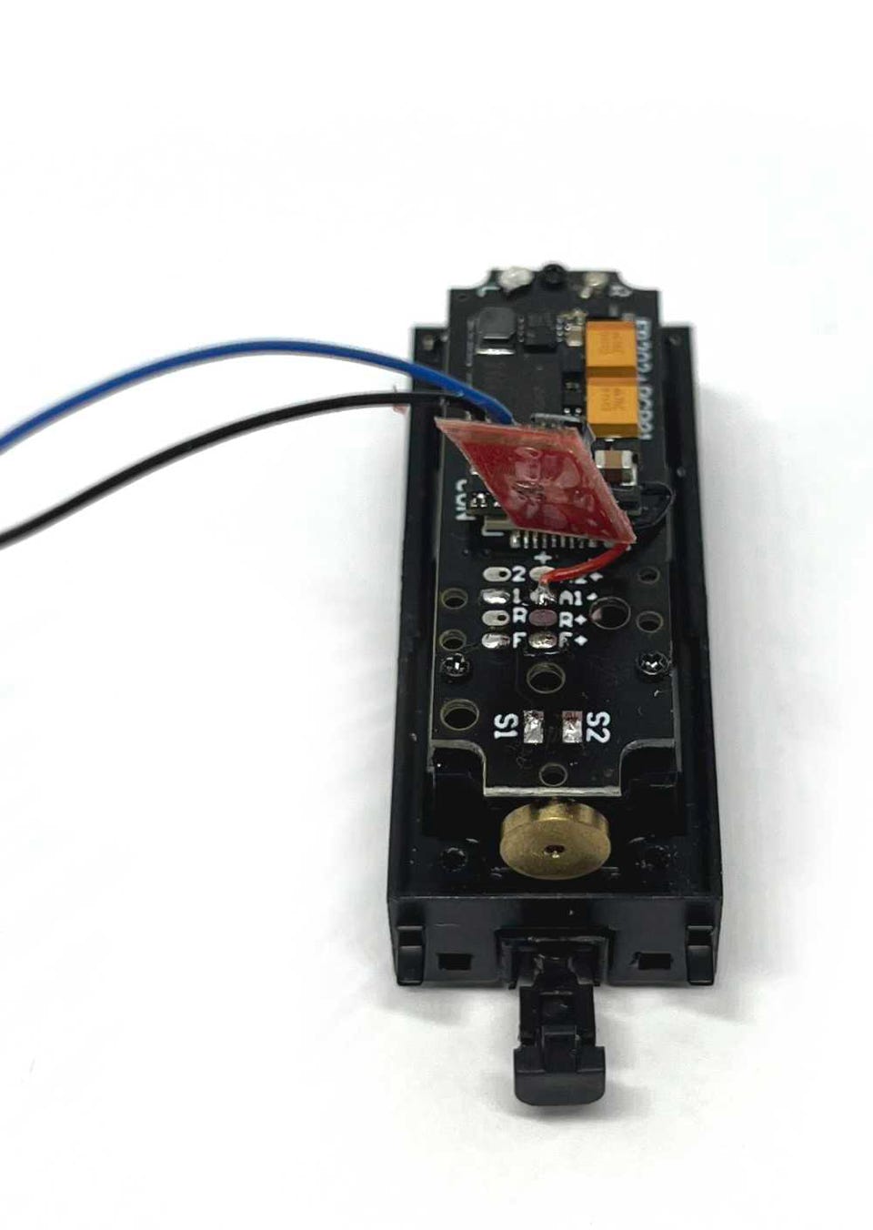
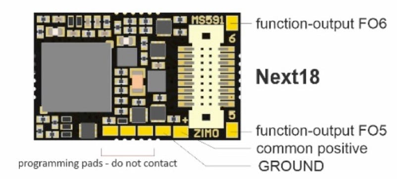
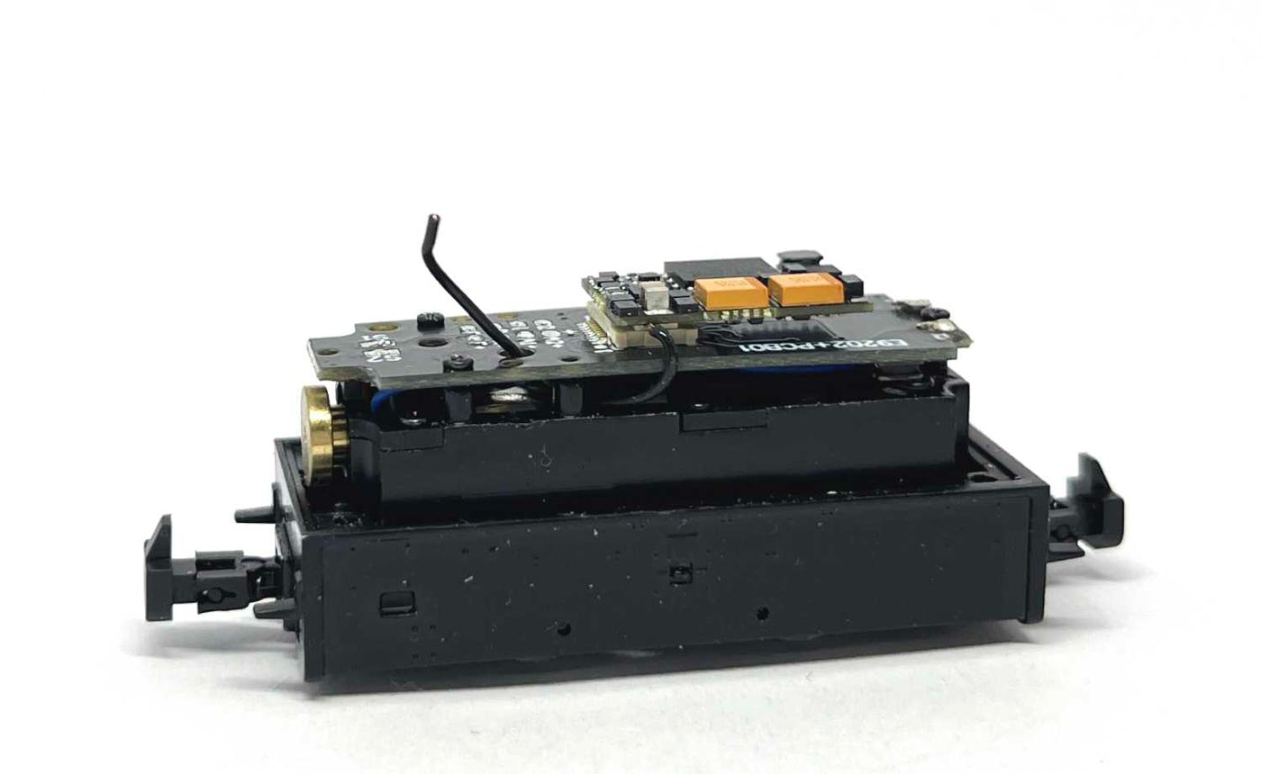
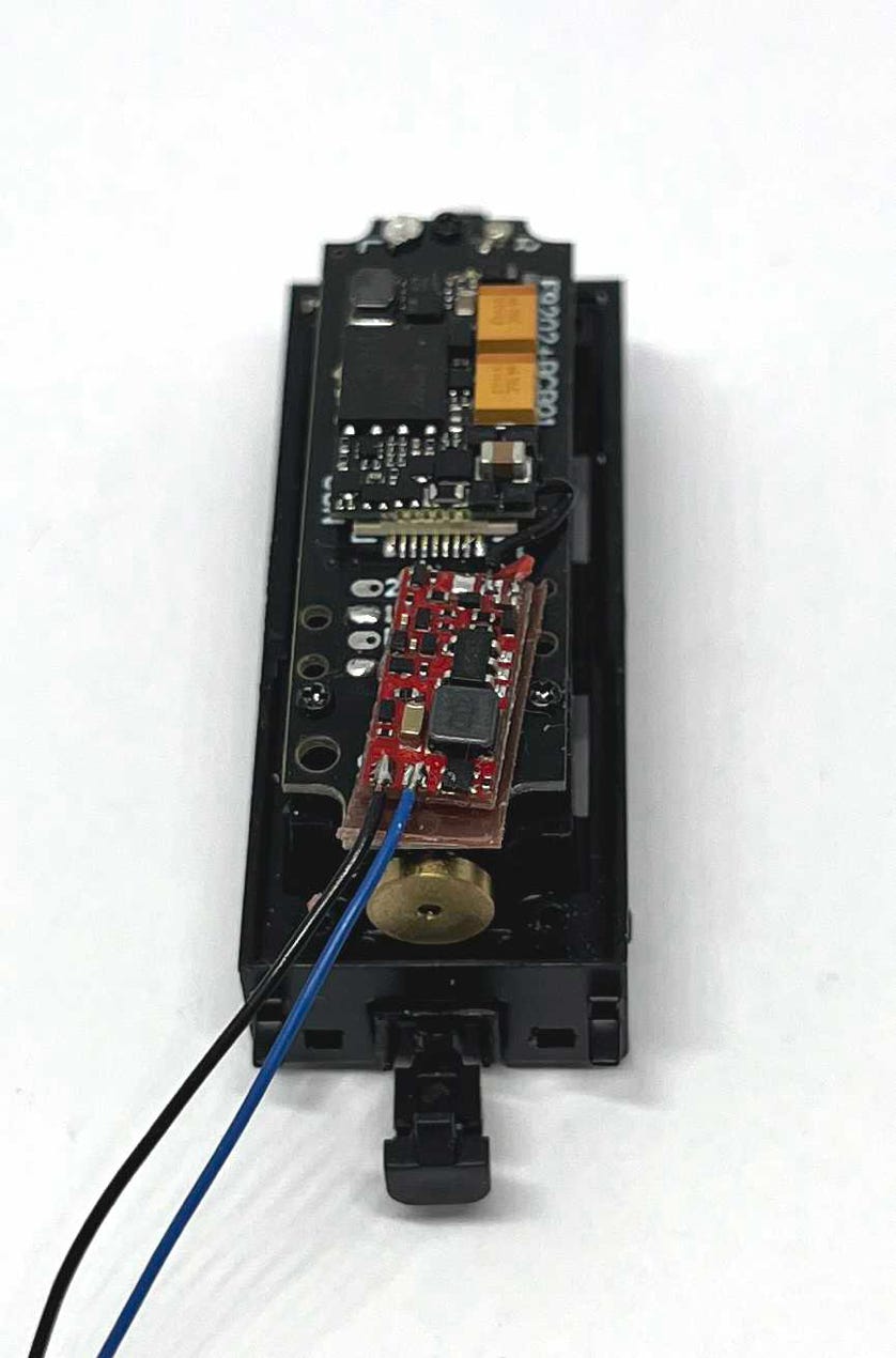
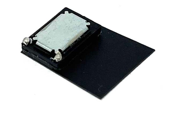
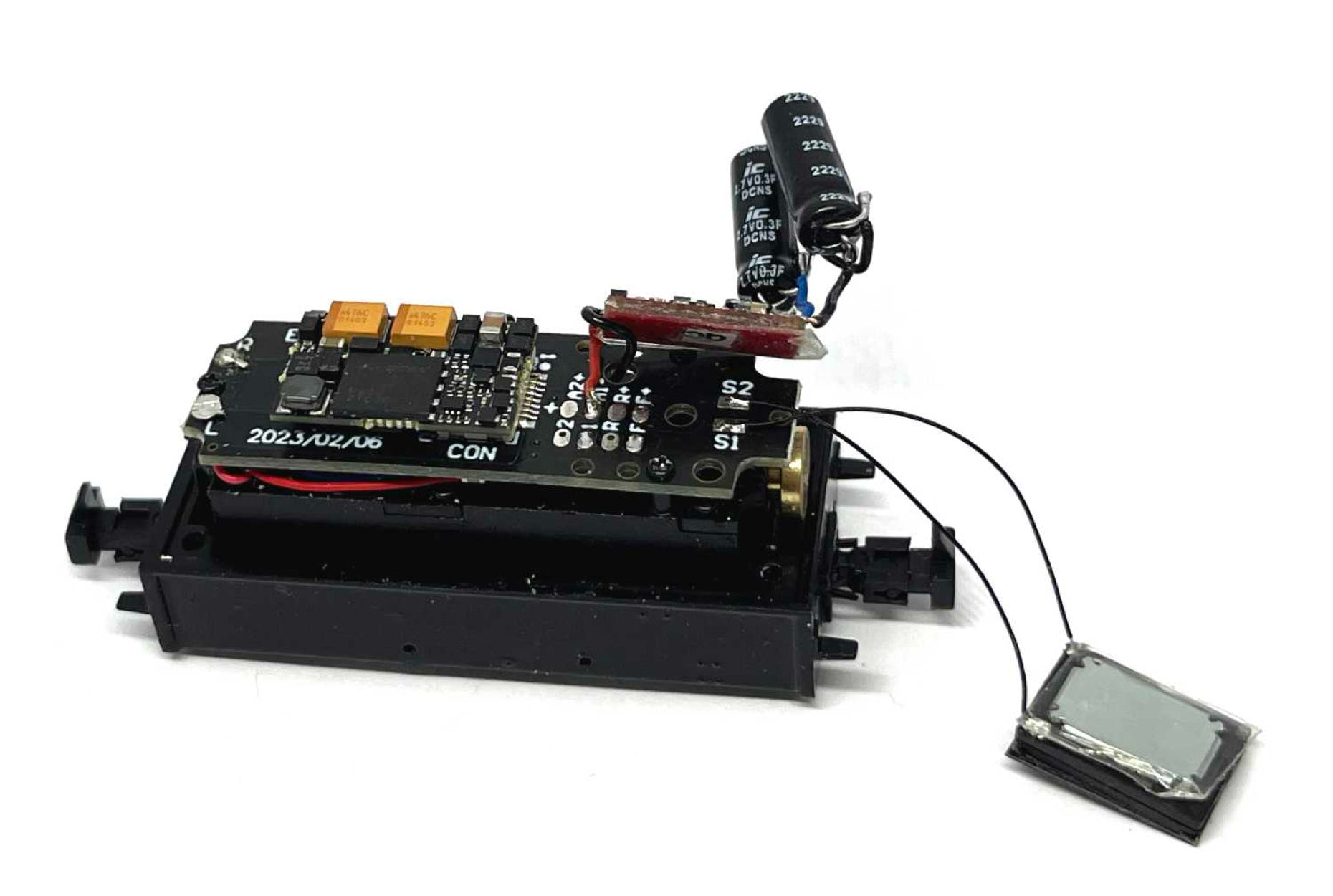
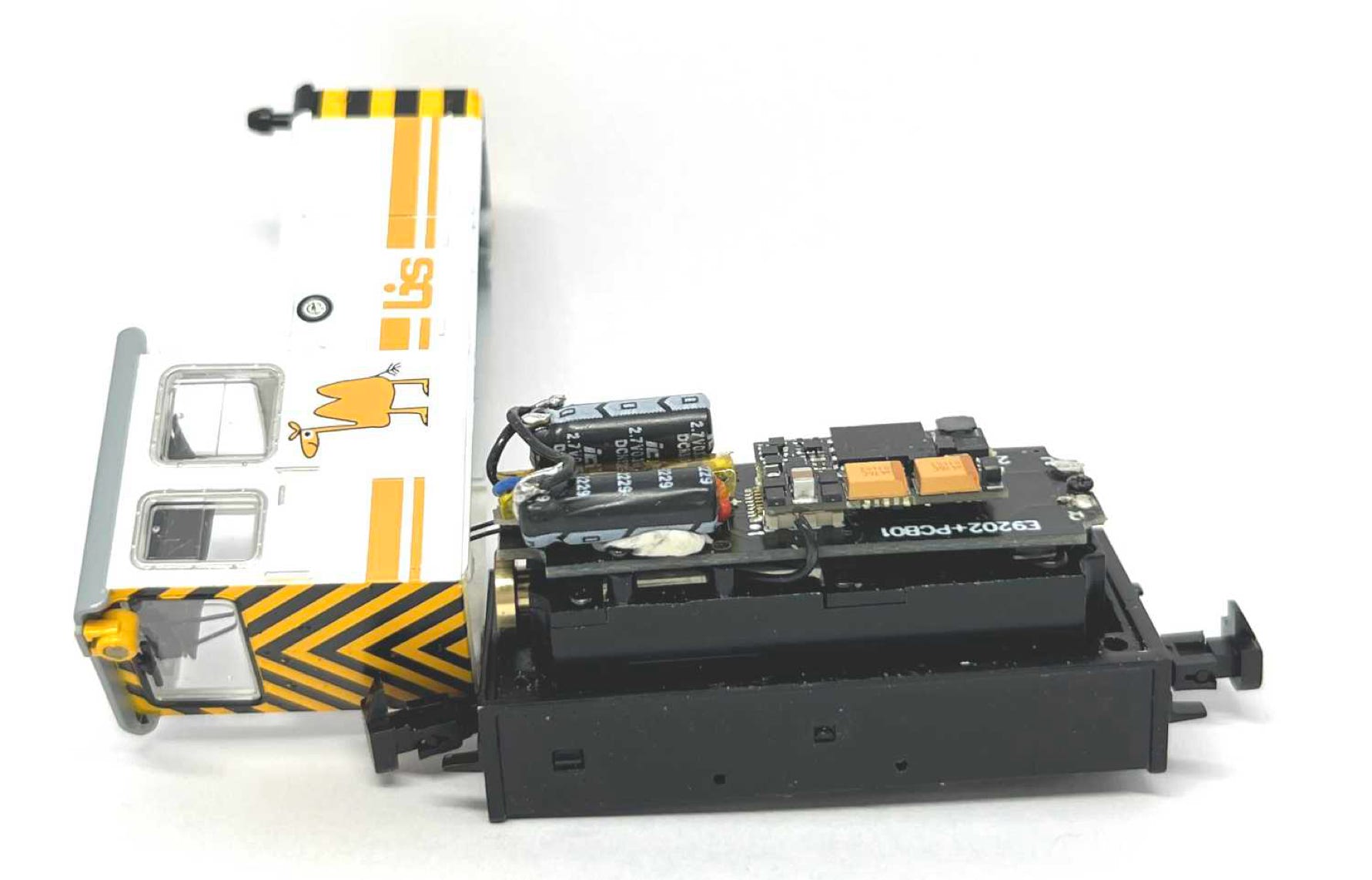
A guide to installing decoder and sound
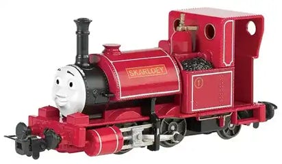
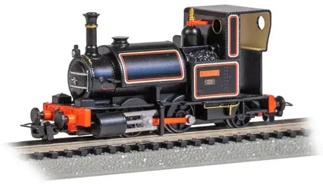
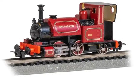
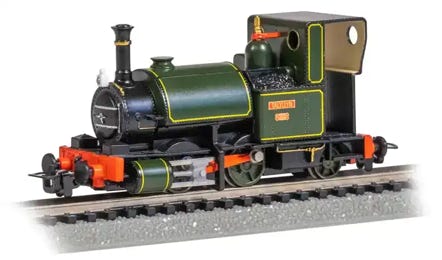
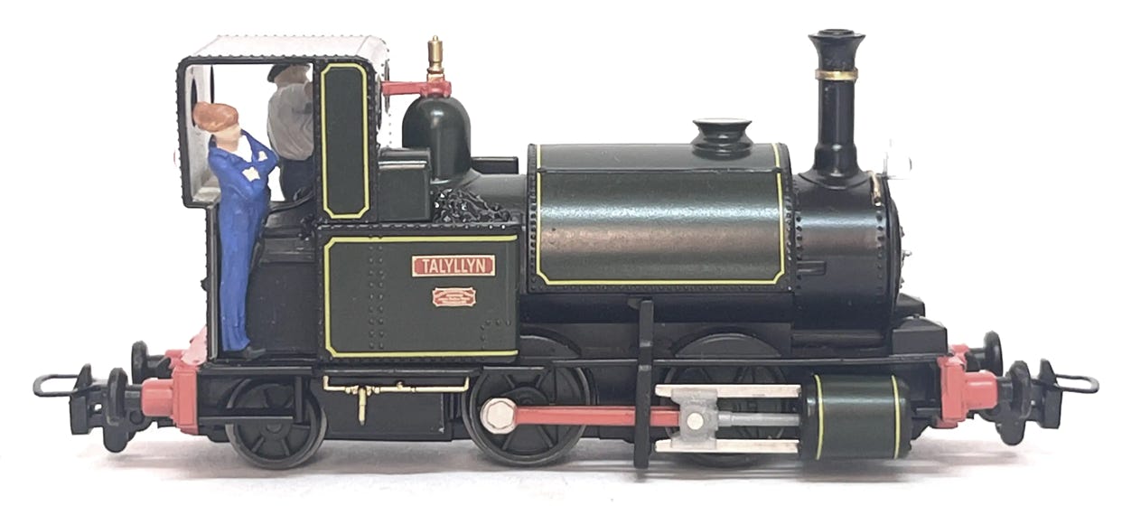
Bachmann Talyllyn/Skarloey
Bachmann initially came out with a toy model of the “Thomas” engine Skarloey. Even though it was a fairly simple model, it wasn’t a bad one. It also had a decent mechanism, so it was well received. People were asking for real world liveries and Bachmann listened. In 2024 they released three version. A green, black and a red one. Below you will find instructions how to take the model apart and to install a better motor, a non-sound or sound decoder and stayalive for a higher enjoyment.
For the sound installation is needed, available from the Tramfabriek:
- Zimo sound decoder MS491
- Zimo STACO4 Stayalive
- Tramfabriek 8 x 13 mm speaker
- Ultra thin wire (black) or thin enamel wire
For the non-sound decoder installation:
- Zimo MN160 or MN150 DCC decoder, or any decoder that is less than 8mm wide.
- Zimo STACO4 Stayalive (I do not recommend installing DCC without stayalive)
For just the coreless motor upgrade:
- Tramfabriek Skarloey/Talyllyn motor upgrade.
Specifications
Length (frame): 61.5 mm
Length over buffers: 72.7 mm
Width: 25 mm
Height: 33 mm
Weight: 64 grams
Wheelbase: 15.7 mm
Wheel diameter: 9.4 + 7 mm
Height in cabine for figure: 23.2 mm
Announced: August 2022
Released: December 2024 (USA)
Take apart - Replacing the motor
Remove the screws at indicated points.
Take the housing off. Remove the screw (arrow) that holds the PCB board. Desolder the wires. You don’t need the screw nor PCB board anymore when you are converting the model to DCC.
To create a much better driving experience (replacement motor runs smoother, is actually quiet, uses less current and has a much lower maximum speed), I advise to replace the motor, if you are going to go DCC. The chuff of the sound file is adjusted to the coreless motor (but you can adjust the chuff speed in CV 267, if you decide to keep the old motor).
During the process, I keep the model on a sheet of foam, to protect it from damage. Though it’s pretty sturdy.
Be aware that the whistle sticks out when you turn the loco upside down.
Remove the metal weight by taking the three screws out that hold it to the chassis.
To fit the motor, two metal parts need to be removed. But if you are going to fit the sound decoder, you need to do some milling or filing before you do that.
First with the chassis. You need to make a little more space at the rear of the motor.
It’s the sticking up piece that you have to remove.
Below I covered the gearing with a tissue, so the small metal pieces don’t stick to the grease. I use a 2.5 mm milling bit. I hold the model with two hands and move it against the milling bit. It’s easier to take thin layers off than to try to do the whole thing in one push. If you have to put force, there is risk you’ll damage other parts. If you take your time, it’s not a difficult job. I advise to wear a dust mask, as the metal particles are very small. And eye protection. The metal pieces are not flying in your face, but Justin Casey.
Now to get the motor ready. It’s easy to remove the worm from the motor. Just slide a sharp pair of tweezers through the gap, push the tweezers forward and you slide the worm (and flywheel; they are two separate parts) out. Make a mental note of the positioning of the flywheel. The deeper part has to be in the direction of the worm, when you place it on the new motor.
Push in this direction.
Again; easy task, but a bit daunting if you have no experience. Press the coreless Tramfabriek motor on the new worm. Use both thumbs to press on the back of the motor. The plastic backing is only fitted with friction and it is impossible to repair it. But if you press with both thumbs to support the back, you should have no problem. The space between motor and flywheel is about 1.3 to 1.5 mm. You can check if you done it correctly by laying the motor in the chassis. The fly lays (and should spin freely) between the pieces of metal.
This is how it looks like when you’re done. Try to place the motor to see if it lays flat.
You can’t just glue the motor in the chassis. You need to glue a piece of 0.25 mm styrene (supplied with the Tramfabriek motor upgrade kit) to raise the motor. Without it, the gears will grind. The piece of styrene is not made to fit yet, so cut it to size so it lays flat on the metal. Then use superglue to fix it in place.
Here’s the piece of styrene glued in its place.
Now fit the motor. It can best be glued with epoxyglue. I use Araldite 90. It dries fast enough for impatient people like me, but not too fast that you can’t reposition it. And if you completely mess up, you can tear it out, clean it up and try again. Align the front of the motor to the metal bracket that’s in front of it. Check if you did the spacing correctly for the flywheel to be able to spin freely. When the glue is drying, hold the motor in place until it has set a bit and check that it is straight. The blue wire will be connected to the right side of the loco, so you can keep the blue wire on the right, but for connecting it later, it doesn’t matter.
When the glue is dried enough after a few minutes, I use a 9V battery to connect to the wires and check how it runs. It should be smooth and as good as quiet. Even at full speed you don’t hear whining, where you would with the original motor.
The metal weight won’t fit now, because of the bar at the end. You can choose to file it so it does fit, or just cut it off. I choose the quick and easy way.
If you are just replacing the motor you can reverse the take-a-part and you’re done. But for DCC and DCC Sound, you need to do a bit or more modification to the metal weight.
The Zimo decoder will fit perfectly in the PCB board slot, but as you need to isolate the decoder from the metal weight, the tape that you put around it will make it a bit larger. So you need to run the milling bit along the indicated edges to make the space. Just test fit with the decoder if you’ve done it right. You also need to take the front bit out and level it with the rest of its surroundings, so there will be enough space for the stayalive board, that goes on top of the decoder.
Explanation of all the connectors.
Aux 1 and 2 are for optional functions. Like interior light, if you want to install this (a LED is required, does not come with the model).
To install a front and rear light, again, you need to bring the LEDs. I would think 0402 warm white LED pre-wired would be a suitable choice.
Here are all the parts of the sound installation.
Installation with Train-O-Matic SPP Nano Stayalive
Zimo Next18 sound decoder
Supercapacitors
+ wire
8x12 mm speaker
- wire (GND)
+ wire
PCB of Train-O-Matic SPP Nano Stayalive
- wire (GND)
PCB of Zimo STACO3A Stayalive
Solder a black wire on the indicated solder pad on the sound decoder. This is the minus (aka Ground) of the stayalive.
Because the housing of the model has a part that reaches the PCB (see picture below), the black wire needs to be guided under the PCB, not over it. See next image.
MS590N18
MS591N18
The black wire then comes up again through the hole.
The black wire is then kept as short as possible and soldered to the stayalive. Then connect the red wire (Train-O-Matic) or blue wire (Zimo) from the stayalive to any of the 4 solder pads in the row with the + at the top. I used one of the top two ones.
Lay the speaker on the supplied sheet of black 0.25 mm styrene. With a brush, run superglue or styrene weld along the edge, to connect these parts air tied together. Then cut the styrene to the size of the speaker. A larger resonator box is not necessary. The cab will serve as one.
Solder wires to the speaker and solder these two S1 and S2. A speaker has no polarity, so it doesn’t matter which cable you connect to which ’S’ solder pad. Use wire as thin as possible, so it won’t be obvious in the cab.
Solder the supercaps to the stayalive.
A piece of thin double sided tape on the metal side of the speaker is sufficient to keep it stuck to the underside of the roof. You can find 0.25 mm double sided tape on eBay (red rolls). I also have put this same tape under the decoder and later, also under the supercaps. Initially I used blu tac, but that wasn’t reliable.
The great thing of the Train-O-Matic stayalive over the Zimo one, is that its form factor is long. With the supercaps they lay nicely next to each other, where with Zimo the supercaps would be more raised.
Re-assembly
Before you stick the speaker under the roof, first test the sound and stayalive. It takes 30 seconds for the stayalive to be fully charged.
Again, pay attention the 4 screws go into the correct hole. Self tapping screws at the rear, machine screws at the front.