


Prices for UK customers are shown inc 20% VAT
Other countries, inc EU, prices shown are ex VAT.
UK based

KASTENLOK INDEX

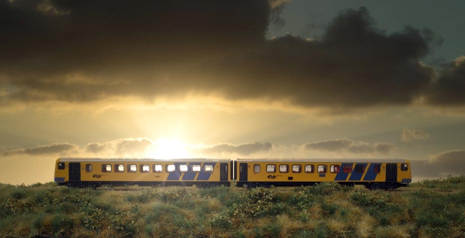
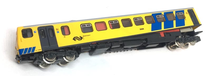
Fleischmann Wadloper Upgrade
to 12V coreless motor
Prices for UK customers are shown inc 20% VAT
Other countries, inc EU, prices shown are ex VAT.
UK based
KASTENLOK INDEX
Fleischmann Wadloper Upgrade
to 12V coreless motor
What you need for conversion set
- The model and upgrade kit
- Small flat screwdriver
- Soldering iron 15W/25W
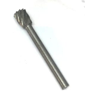
- Milling bit with flat head
Installation time: Around 40 minutes
Difficulty: Pretty easy to do. Don’t let the milling scare you off. With the right milling bit, it’s easily done.
2
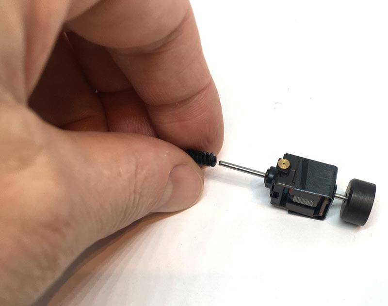
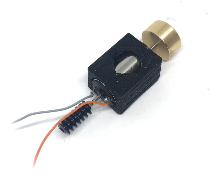
Stel de motor samen zoals op het plaatje. De motor heeft een kleine plus (+) naast een van de connectors. Dat is het oranje draadje op het plaatje. Om er zeker van te zijn dat je model in dezelfde richting rijdt als je andere treinen, zorg ervoor dat de plus aan dezelfde zijde zit als op het plaatje). Waarschijnlijk heb je geen lijm nodig om het vliegwiel en de wormadapter vast te zetten en zit het al met frictie vast. Maar zit het toch te los, een beetje Loctite of superlijm gebruiken. Wel eerst controleren of ze op de juiste plek zitten, door het in het model te passen.
Fits Fleischmann 7471
1
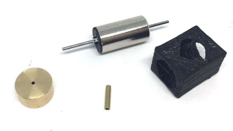
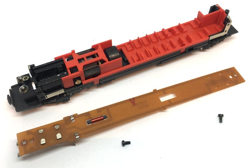
Contents of the kit
You’ll need to get a milling bit like this, from for example eBay >>>
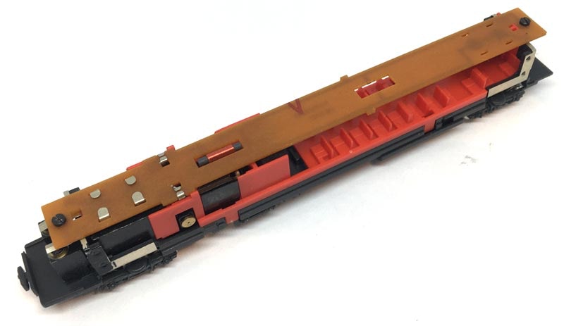
To open the model. Easiest is to use cocktail sticks on the four locations indicated. Then you can easily pull the chassis out.
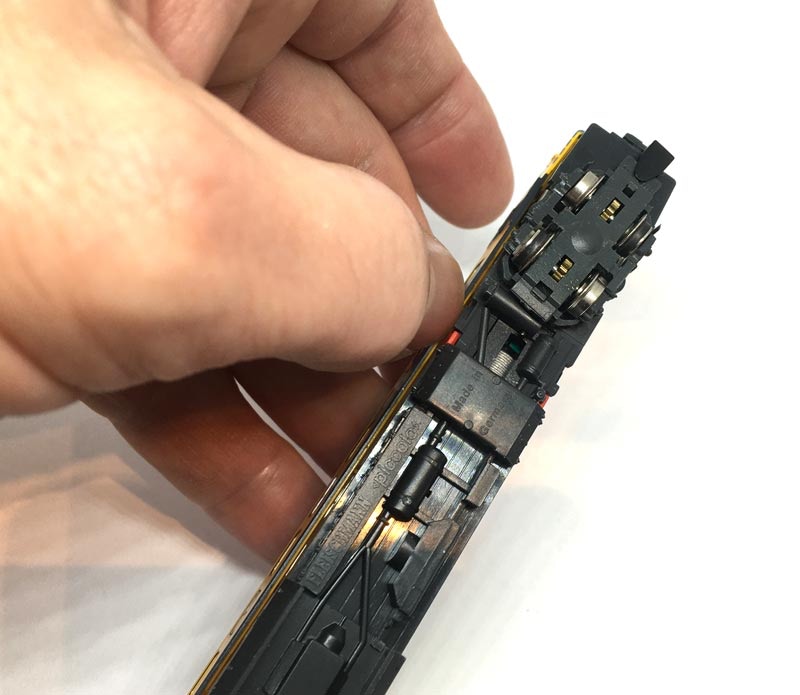
Om het model open te maken is het het makkelijkst om vier cocktail prikkers op de aangegeven plekken te plaatsen. Je kunt het onderstel dan makkelijk uitnemen.
Remove the two screws and take the electronics board off.
Verwijder de twee schroeven om het printplaatje los te halen.
3
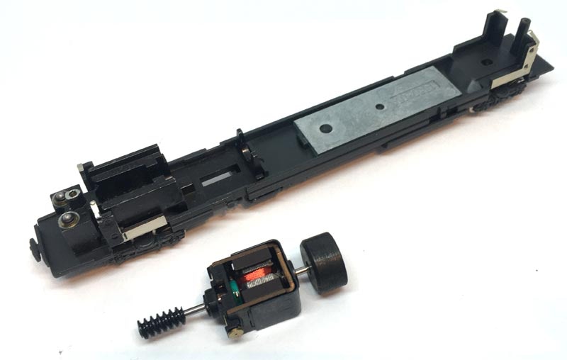
The orange plastic with the seats needs to be taken off. There are three clips on both sides. Carefully lift them away from the chassis to release them. You can then lift the motor out.
4
5
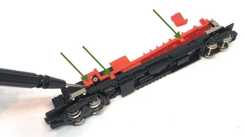
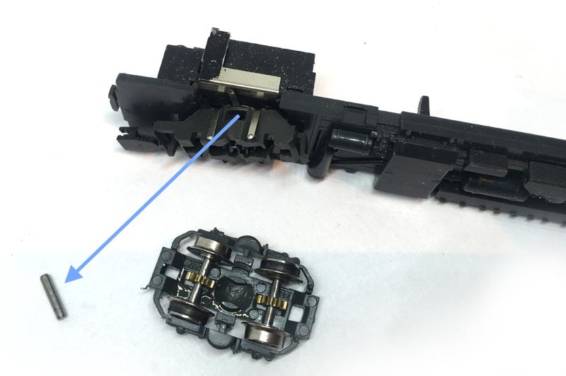
Om het chassis klaar te maken voor het frezen, moet het draaistel er af. Als je het laat zitten, komen alle flintertjes die van het metaal afkomen in het loopwerk te zitten. Trek de onderkant van het draaistel los, dan verwijder de pin die het draaistel op zijn plaats houdt. Als de pin er uit is, kun je de rest van het draaistel verwijderen. Haal ook het grote, zwarte rad er uit dan door de pin op zijn plaats werd gehouden.
To prepare the chassis for milling by removing the bogie. Milling will cause a lot of small particles of the metal frame to go every where and you don’t want this in the gearing.
You do this by removing the bottom of the bogie, which will reveal a pin. Push out the pin, indicated on the image. The the rest of the bogie can be taken out. Also remove the large black gear that the pin was holding in place.
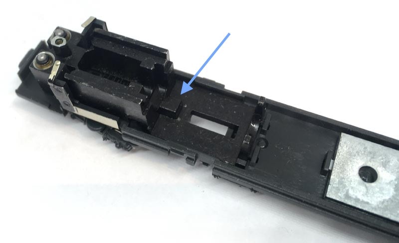
Only the Tramfabriek upgrade kit is designed so that there is a minimale need for milling. Only the piece indicated needs to be removed. Watch the video to see how you can do it in an easy way, if you don’t have any or little experience. I have only done such a thing once before, so it really isn’t difficult. Don’t forget to put (safety) glasses on, to protect your eyes from small metal pieces. It’s more messy than dangerous.
Alleen de Tramfabriek upgrade kit is zo ontworpen dat er maar minimaal gefreesd moet worden. Alleen het stukje dat aangegeven staat op het plaatje moet worden weggehaald. Bekijk de video om te zien hoe je dat eenvoudig kan doen, als je er weinig of geen ervaring mee hebt. Ik heb het maar één keer eerder gedaan, dus het is niet moeilijk. Wel even een veiligheidsbril opzetten voor eventueel rondvliegende snippertjes. Het maakt meer een rotzooi dan dat het gevaarlijk is.
Milling Frezen

6
8
Assemble the motor like on the picture. The motor has a small plus (+) next to one of the connectors. That is the orange wire on the picture. To assure your model drives in the same direction as your other trains, make sure the plus will be on the left side (seen in forward direction of the train). You probably don’t have to glue the adapter on the motor shaft, nor the flywheel and they’ll fit with a push fit. If you need glue because one of the items moves easily, use Loctite or superglue. But first test fit the assembly in the chassis to make sure everything is on the right place.
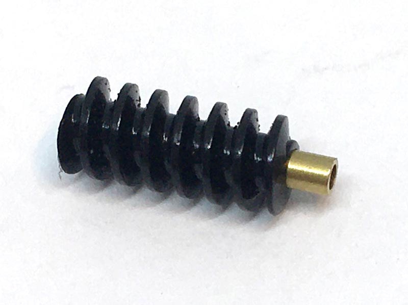
With your fingers, pull off the worm from the original motor shaft.
Trek met je vingers de worm van de motor af.
Question? Just reach out!
De originele motor wordt eruit gehaald door drie clips aan elke zijde los te maken. Voorzichtig, zodat ze niet te ver worden gebogen of afbreken. Dan kun je de motor uitnemen.
A

B
7
Press the worm on the brass adapter.
Druk de worm op de messing adapter.
9
10
11
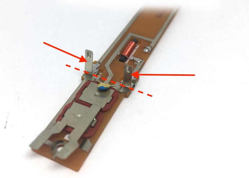
Cut of the two contact strips.
Knip de contactstrippen af.
12
BONUS
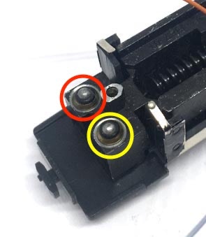
If the lights have dropped out while you were working on it, here’s a reminder where the white and red light bulbs go.
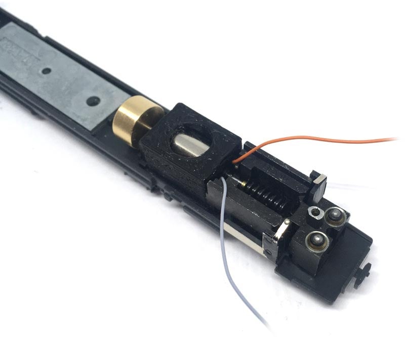
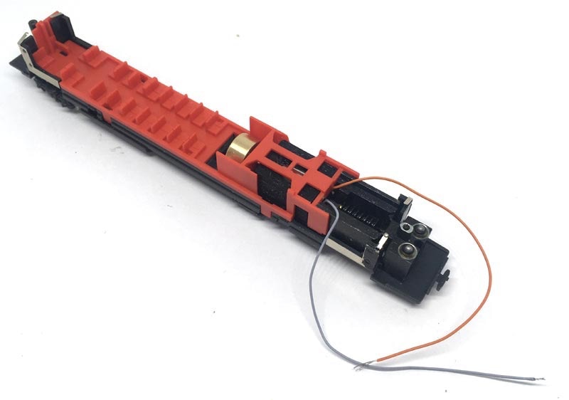
Press the motor assembly inside the model. The casing will fit right in place. Position the flywheel so that is doesn’t touch the chassis metal or plastic orange cover and assure the worm is centred above the gear (the bogie can be replaced now for this).
Make sure the motor contacts don’t touch the metal chassis. You probably will have to bend them a bit inwards.
Druk de motorcombo in het model. Zorg dat het vliegwiel zo gepositioneerd is dat het het metaal van het chassis en het oranje plastic niet raak. Schuif de wormadapter zo dat de worm recht boven het tandrad (het draaistel kan ondertussen weer teruggeplaatst worden).
Let er ook op dat de contacten van de motor het metalen frame niet raken. Je zult ze lichtjes naar binnen moeten drukken.
Place the orange cover. Note how the wires are guided.
Plaats het oranje plastic. Let op hoe de kabels uit het model worden geleid.
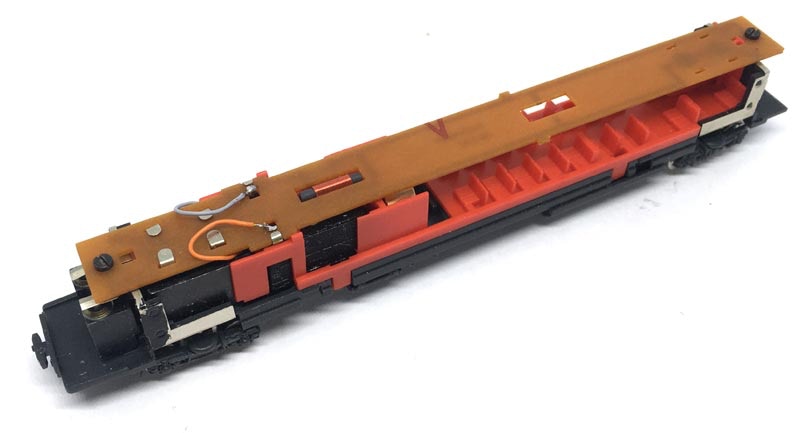
When you have secured the electronics board with the two screws (M1.6, if you lost one), solder the wires on the board where the contacts for the previous motor are.
The motor can also be controlled with a digital decoder. The CV settings for several brands are listed here.
Als je de printplaat op zijn plaats hebt bevestigd met de twee schroefjes (M1.6, als je er eentje kwijt bent geraakt), soldeer dan de draadjes waar de contacten voor de oude motor zijn gesoldeerd.
De motor kan uiteraard ook digitaal aangestuurd worden, de CV instellingen voor verschillende merken staan hier.
Als tijdens het werken de lampjes eruit zijn gevallen, hier is een geheugensteuntje waar het rode en witte lampje gaan.
Digital conversion
This motor upgrade kit can very well be converted to DCC. Check the digital setting page, for many decoders, to get the best driving experience.
Deze motor upgrade kit kan ook aangestuurd worden door DCC. Kijk op de digitale instellingen pagina voor de CV instellingen voor de grote decodermerken, om de beste rijervaring te hebben.
And one more model has been brought back to the future!
•