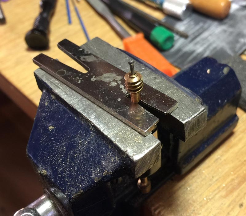
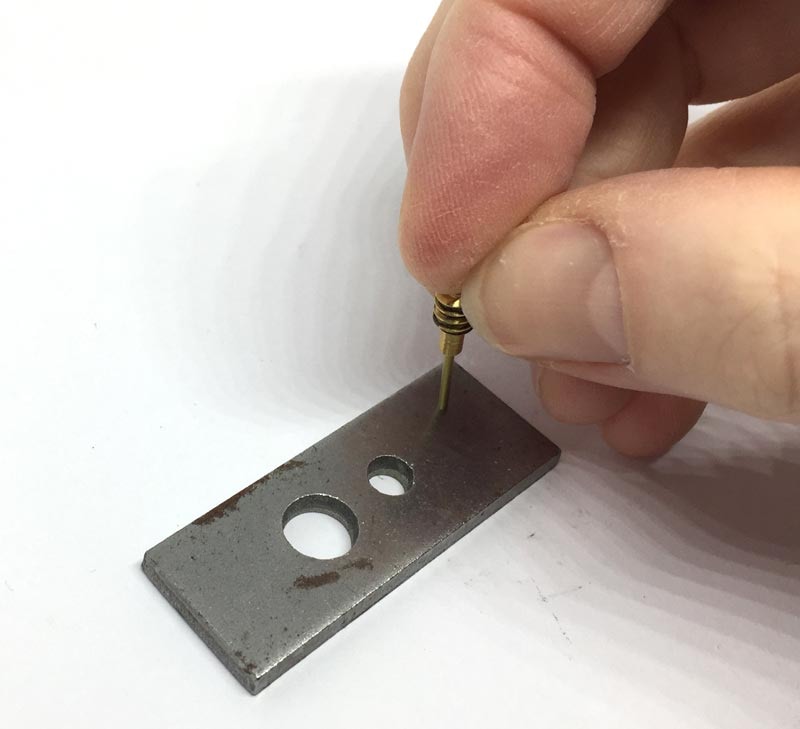
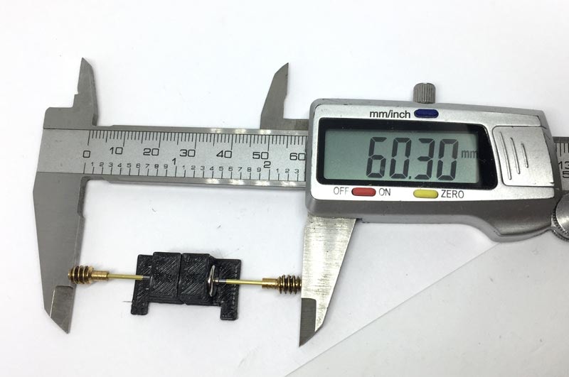
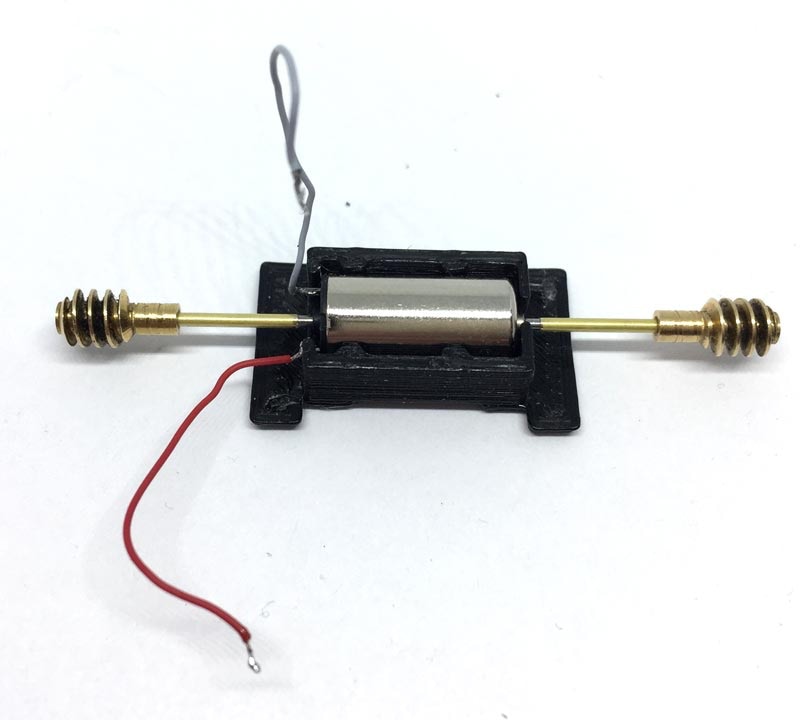
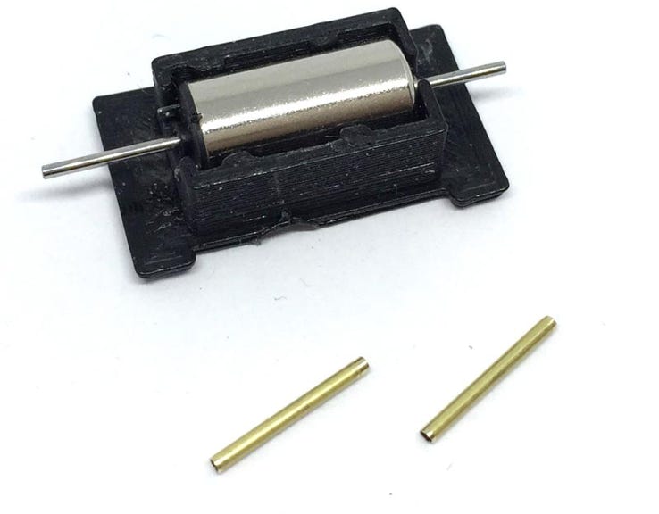
Conversion Minitrix V160 ‘Lolo’

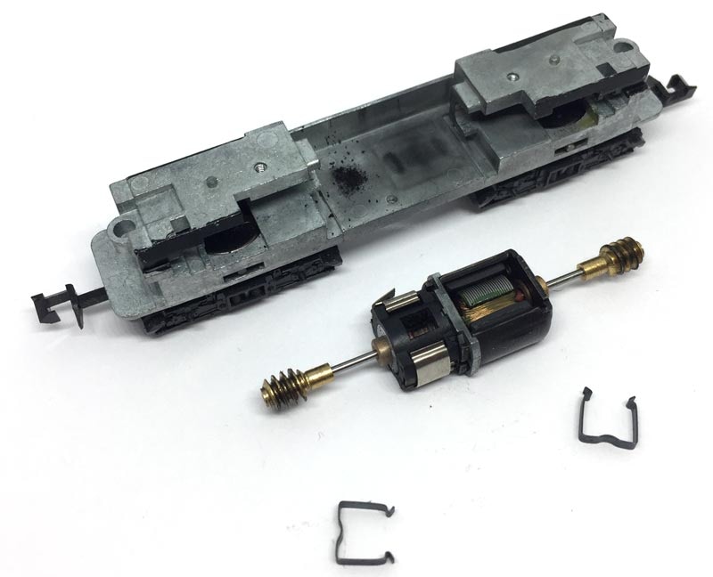
to 12V coreless motor

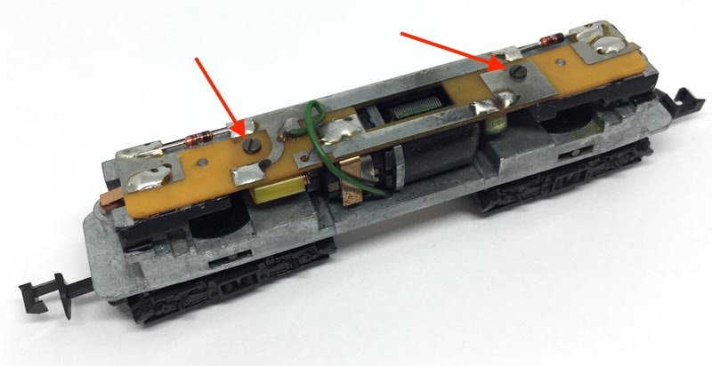
Fits all Minitrix art. 11107, 11108, 12423, 12460, 12461, 12501, 12846, 12874.  Will even be suitable to similar designed Minitrix locomotives (compare inside of your model with the pictures).

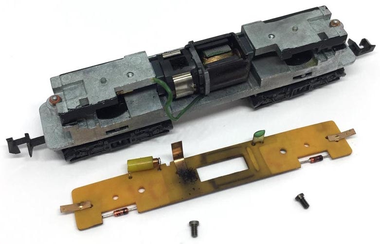
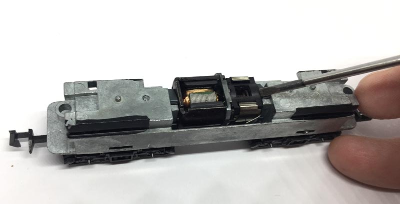
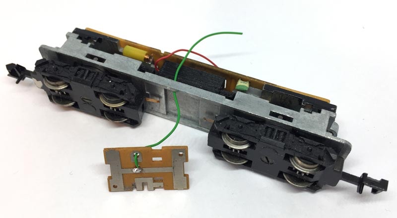
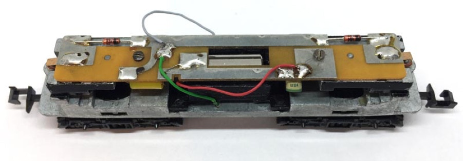
Original frame. Compare your model to see if it is similar.

KASTENLOK INDEX

Question? Just reach out!

What you need for conversion set

- The model and upgrade kit

- Small flat screwdriver

- Soldering iron 15W/25W


Installation time: Around 45 minutes

6

1

3

4

Take the housing off by bending the sides outwards with the nails of your thumb, then pull a bogie towards you to lift the chassis out.

Take the electronics board off and the two metal block out. Put the two light bulbs aside (at the ends of the model), you might loose them.

Use a flat screwdriver to remove the two clips that are holding the motor in place.

Remove the two worms from the motor. In this case, I’ve cut a nail that fits in there, just sticking out a little higher. You can read more about removing worms and gears in this article on this website, a MUST READ.

2

Remove the two screws

5

This is what you are left with.

7

Important: it is best to clean the holes with an 1.2 mm drill bit or better, a reamer (by hand, in a vice). The walls of the brass adapter are only 0.1 mm thin, so if you would push with force, you’ll damage the adapter.  Ideally, the worm has to slide on and glued with Loctite.

9

Slide the whole assembly in and test it running. You might not have to glue the adapters, as they are most likely a tight fit. But if you do glue the adapters, slide them first on, about 5 millimeters from the motor. Then put a tiny bit of Loctite or superglue on the shaft, so only about two millimeters will be glued. If you would put glue inside the tube before sliding it on instead of on the shaft, you would run the risk the tube is stuck before you reach it intended position. When pushing on, leave enough space not to push the glue in the motor. Leave it to dry.

Carefully press the worm on the brass adapter until you can’t get it further, which is about 4-5 millimeters. Do this for both worms.

Solder the wires. Not that there is a small plus (+) indicating the positive connection. As the motor comes pre-fitted in the housing, we should have fitted the motor so the right contact is the +.

8

Fit the worm/brass tube assembly on the motor shaft, to check if the worm sits centred above the gear. Route the red and green wires through the gap before you push the motorblock in.

Check alignment of the worms on the gears for exact placement of the worms/tubes.

10

11

Now it’s time to close up the patient. Slide the motor back in, noting the routing of the grey (-) cable. It will stay on this side. 

Don’t forget to put the light bulbs back!

12

Solder the motor wires to the locations as on the picture. Check that it is going in the same direction as your other trains and the correct light turns on, otherwise you’ll have to swap the connections around.

And one more model has been brought back to the future!

Digital conversion

This motor upgrade kit can very well be converted to DCC. Check the digital setting page, for many decoders, to get the best driving experience.

Deze motor upgrade kit kan ook aangestuurd worden door DCC. Kijk op de digitale instellingen pagina voor de CV instellingen voor de grote decodermerken, om de beste rijervaring te hebben.