KASTENLOK INDEX

Conversion Kato 11-103 + 11-104

to coreless motor

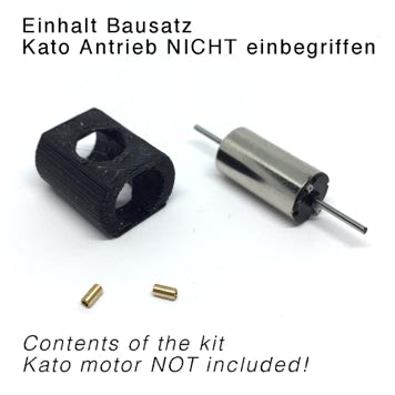
What you need for conversion set

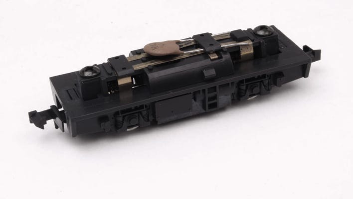
- Kato motorised chassis 11-103 or 11-104

- Small flat and cross head screwdriver

- Soldering iron

- Thin wire


Installation time: <30 minutes

1

Take drive apart

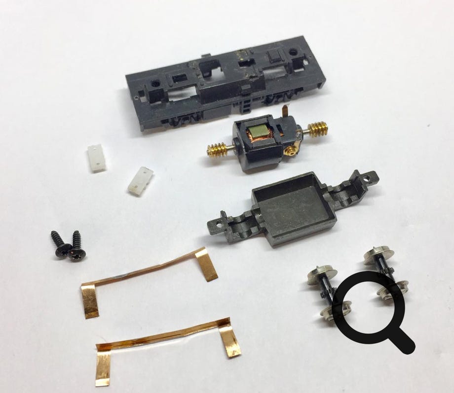
First, remove the couplings. Just pull them downwards, they come off. By removing the two screws on top of the drive, you can take the whole thing apart. You don’t have to take the contact clips off, in contrary to what is shown at the right. You only need to remove one of the two white, plastic rectangle bits on top, which holds the contacts for the motor. This is just clipped in. By putting a flat screwdriver under one side, you can easily lift it off.


Then remove the wheels and take out the motor.

2

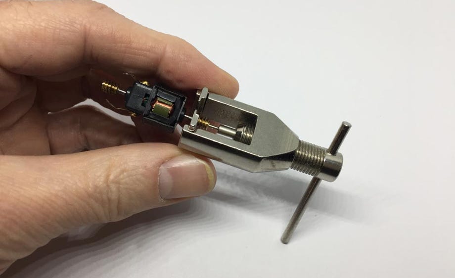
Remove worms

By using a gear puller (available here), the worms come off easily. They are not so tight fitted that you will brake anything.


For more valuable tips how to remove a worm, gear or flywheel, click here.

3

4

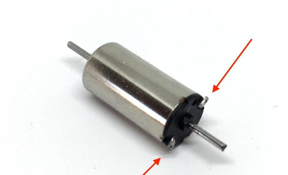
Angle motor connection points

To avoid contact with metal in the chassis, angle the terminal points about 90 degrees if this hasn’t been done yet. Use a flat screwdriver for this.

Check the height of the adapter (black adapter only!)

The following is for the black motor casing only! If you have the grey adapter, you can skip this step)

 As the 3D printer can’t print exactly the correct size for this adapter, you need to sand the flat sides of the adapter (Check the height with a calliper, it’s probably about 10.1 mm. The motor is 9.5 mm high. So sand both sides, so the height becomes at least 9.6 mm. Sandpaper grade 400 or 600 will do.

5

6

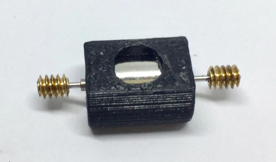
Fit the worms

The holes of  each worm on each side is different in size. Find the smallest hole, which will assure a tight fit of the brass adapter. Then press or hit it with a small hammer carefully (straight!) in place. The distance between the end of the two worms has to be 33 cm. (in later kit version, we’ve been supplying brass adapters that slide in and need to be glued with superglue, not hammered in)


You might need to smoothen the edge of the shaft on the connector side with a file, although we try to ship them with this already done, to be able to slide the worm with fitted adapter on. This side of the shaft has been cut off to reach the required length.


Ideally, turn a 0.99mm reamer through the brass adapter/worm assembly, for an easy fit on the axle. If you have problems fitting it, contact us and we will help you.

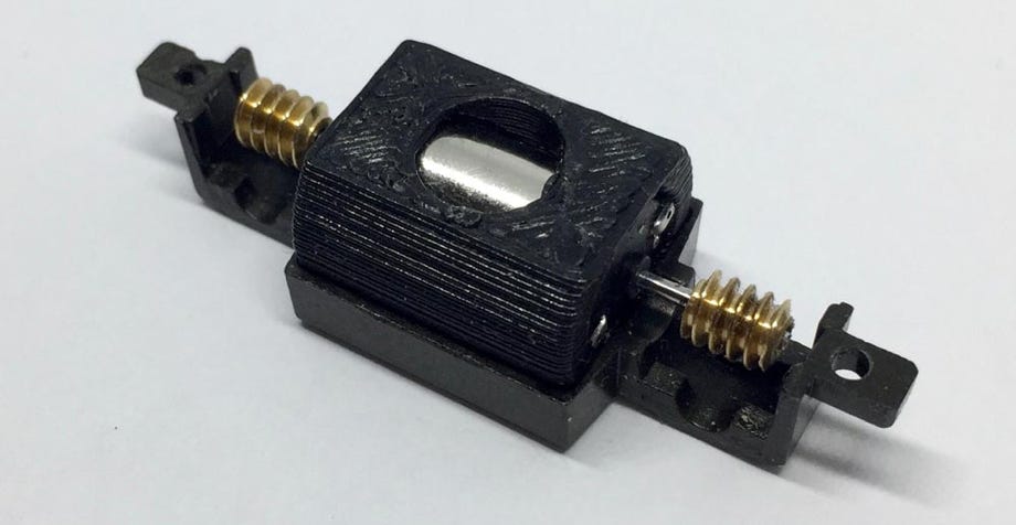
Check correct alignment

You can check for the right alignment with the axles of the wheels with the bottom cover (or just put it back in the chassis).

7

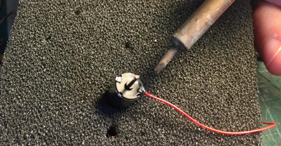
Solder the wires. There is a small + on the back of the motor to tell what is, well, the plus. You don’t have to take the motor out of the housing, nor you have to remove the worms, as it seems in the picture at the right. I hold the whole assembly in a vice on its side for easy soldering.


The Tramfabriek sells ultra thin wire, extremely appropriate for this job.

Solder the wires

8

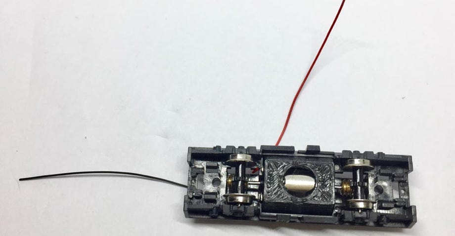
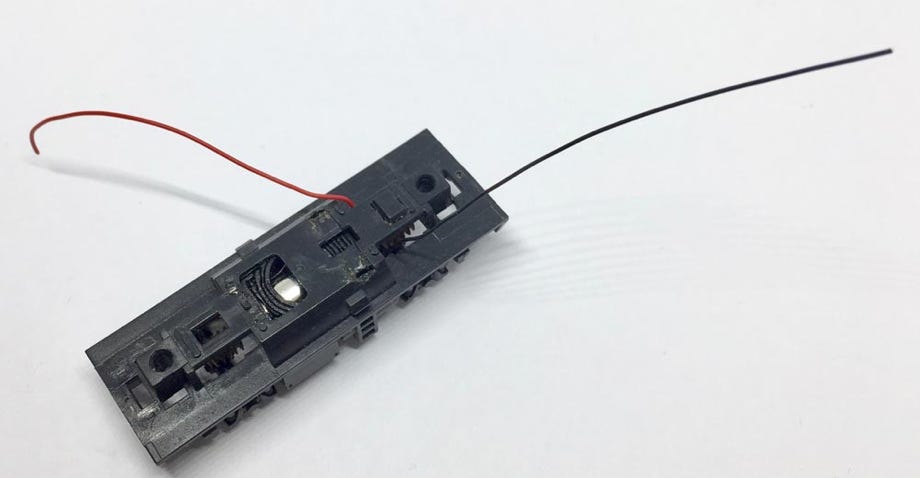
Place the motor assembly in the chassis

Guide the wires through the plastic ( you might have to widen the space) and fit the motor and wheels. 


Fit the bottom cover back under the model.

9

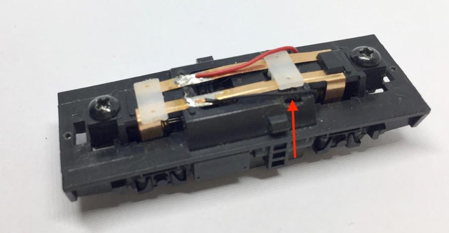
Solder wires to the contacts

From the two contact strips, cut off the part that was sticking inside the chassis to make contact with the old motor. Put the contact strips back in place, taking care that the end contacts go on the inside of the disc wheels.


The clip the white rectangle pieces back in place and solder the wires to the contact strips. Check on the track if it drives in the same direction as all the other trains. Otherwise you’ll have to switch the wires.

Done!

You’re ready. Enjoy the much improved driving qualities!

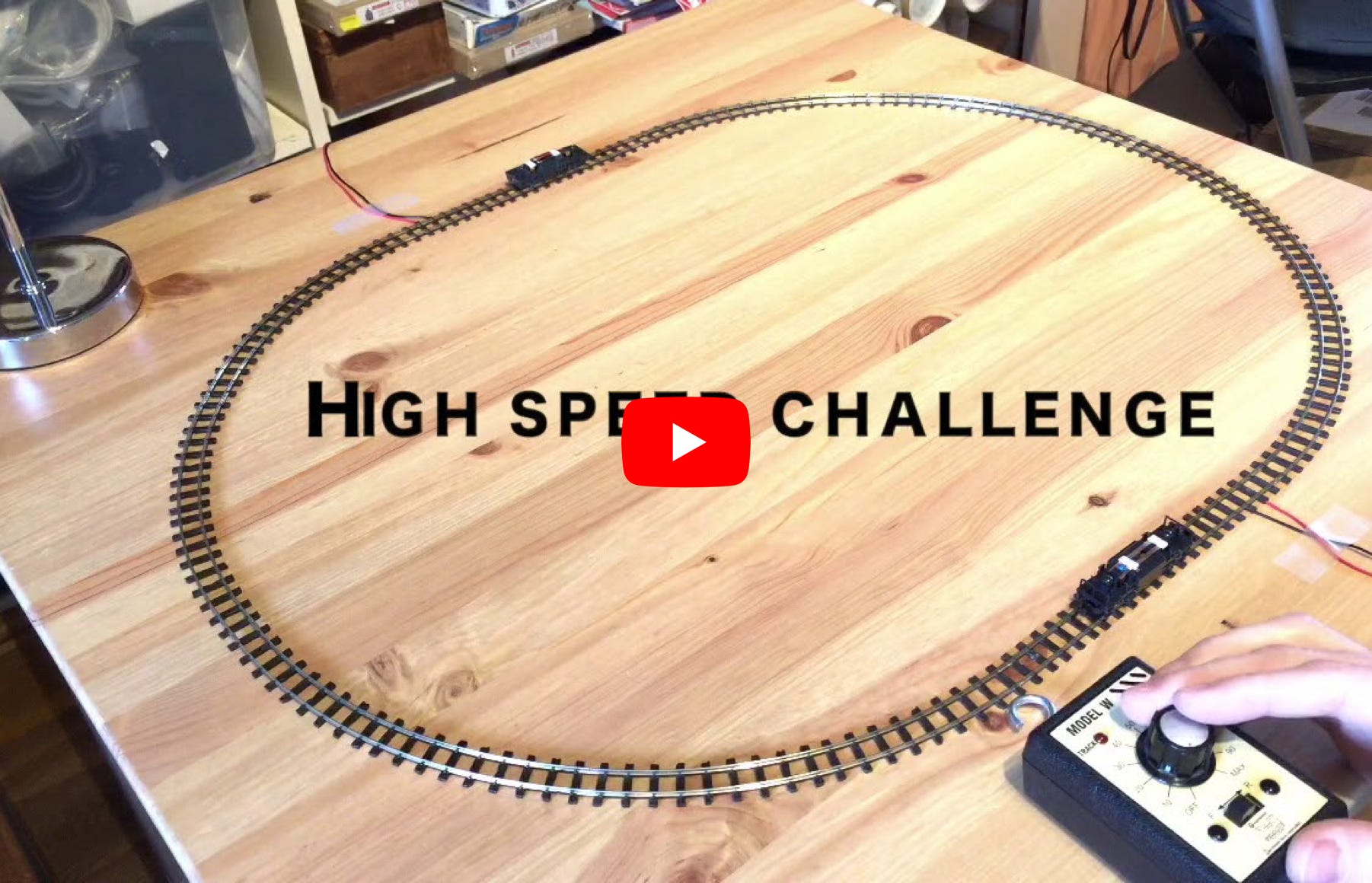
Video