ATTENTION! I AM CURRENTLY AWAY, SO NO ORDERS WILL BE SENT OUT. SHIPPING RESUMES FROM THE 25th OF APRIL 2024. Thanks! Sven.

Prices for UK customers are shown inc 20% VAT
Other countries, inc EU, prices shown are ex VAT.
UK based
-
HOME
-
PRODUCTS
-
DIGITAL
-
PROJECTS
-
Dioramas!
-
Free DCC Sound files
-
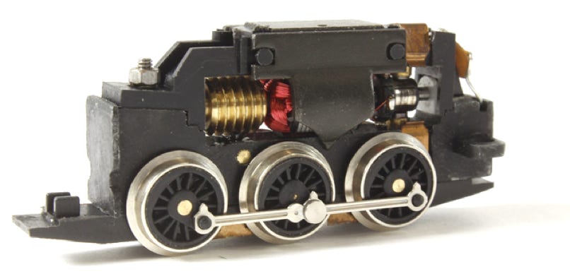
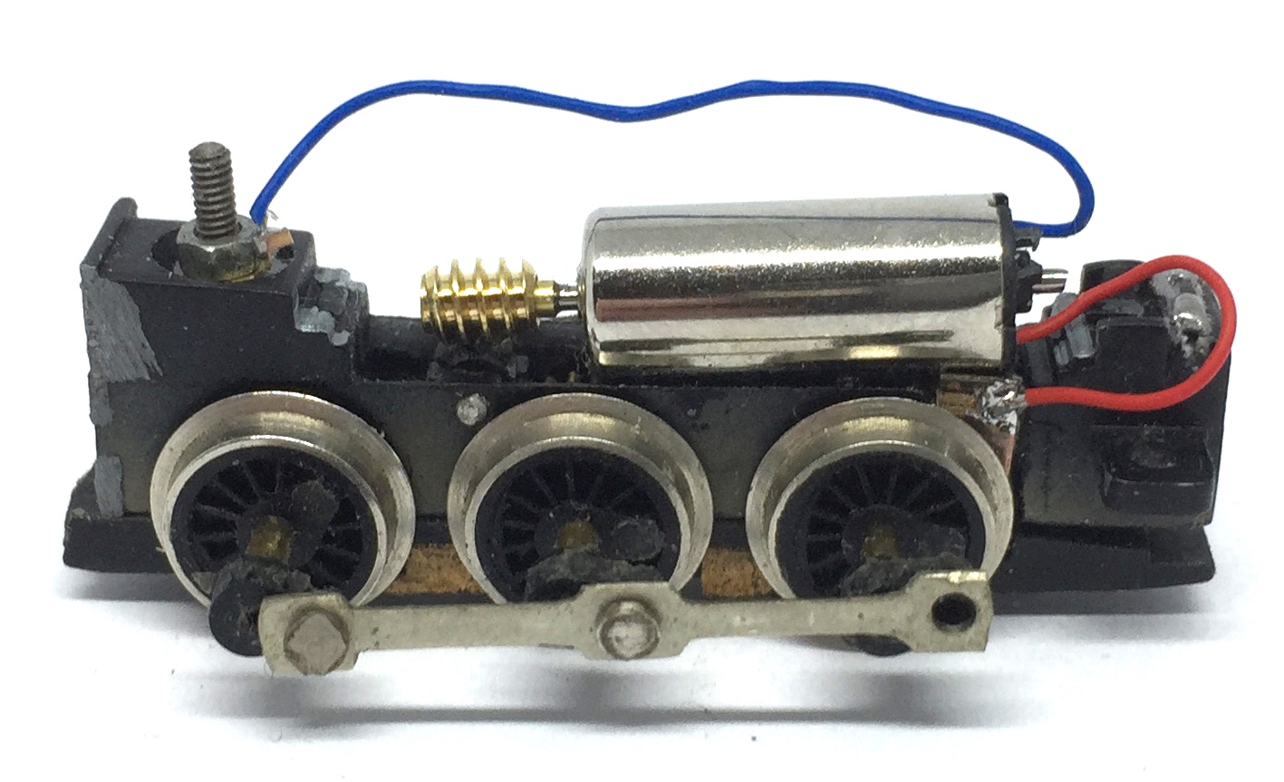
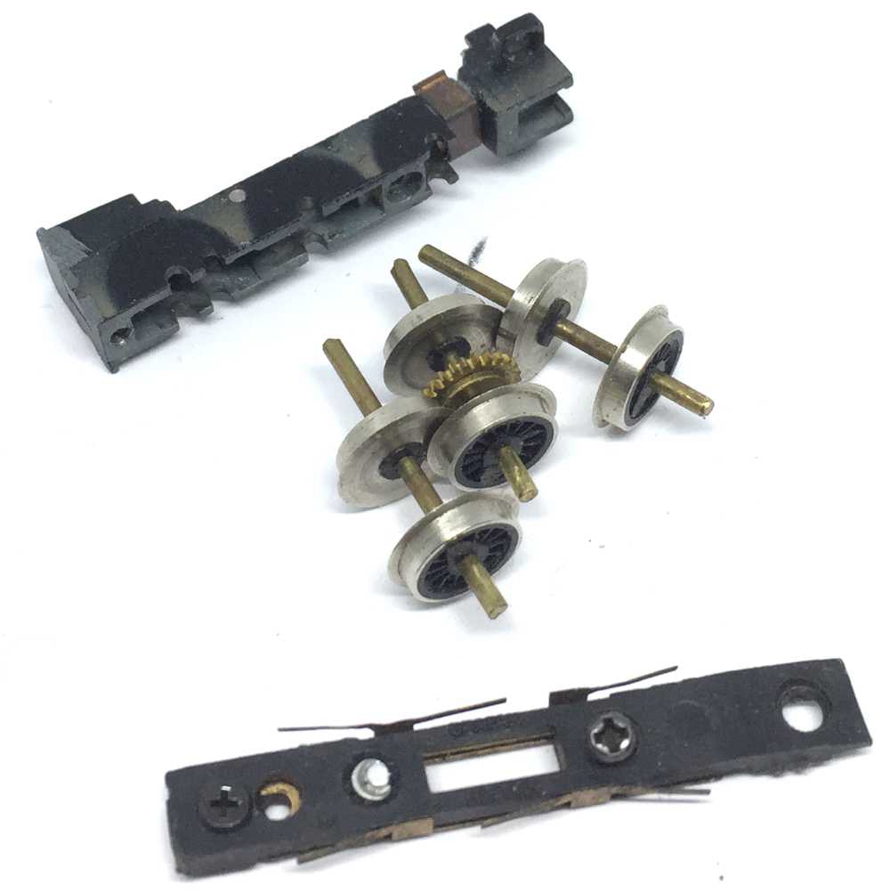
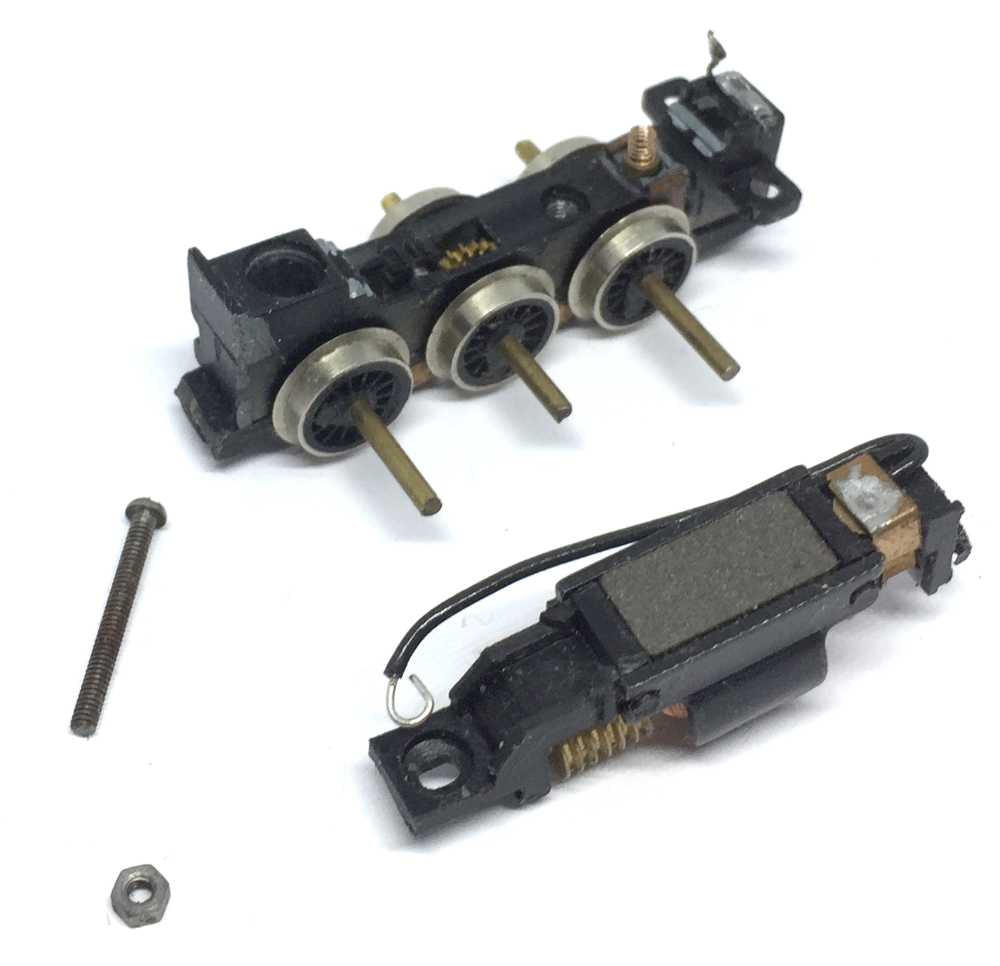
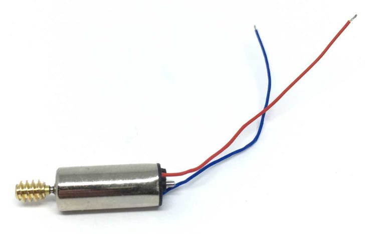
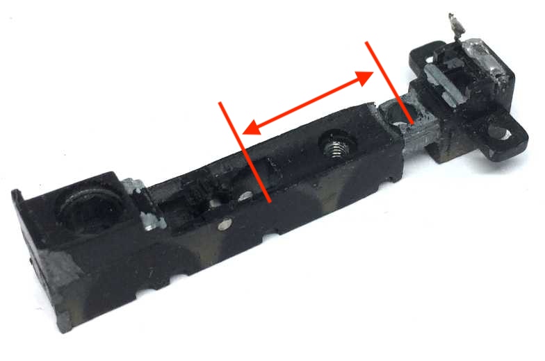
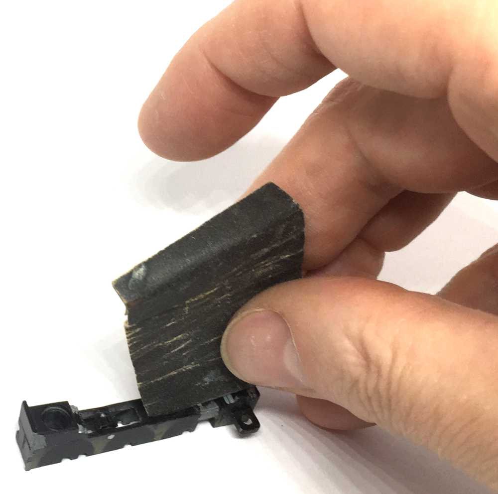
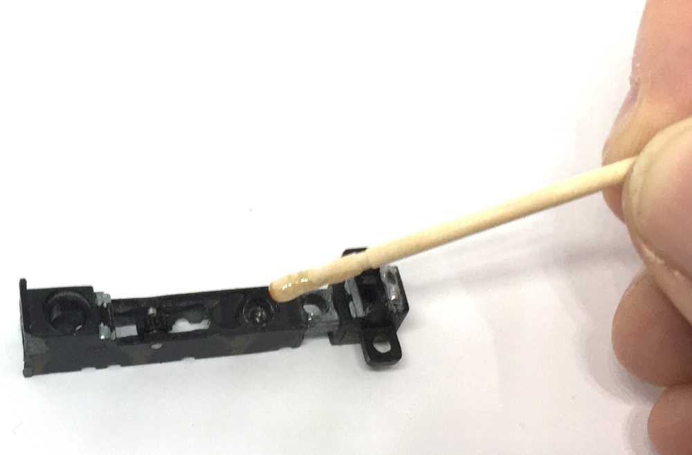
Bachmann Baldwin 009
-
Bachmann Quarry Hunslet
-
Bachmann Mainline Hunslet
-
Diesel Inspection car
-
Heljan Baldwin 009
-
Heljan Manning Wardle problems
-
Kato Class 800 upgrades
-
Kato Take-a-part
-
Minitrains Decauville
-
Minitrains Tramway
-
Liliput H0e coach interior
-
Pacer 009
-
Tillig T1
-
-
TIPS
-
NEWS
-
ORDER
-
MORE
-
SERVICE
-
HOME
-
PRODUCTS
-
DIGITAL
-
PROJECTS
-
Dioramas!
-
Free DCC Sound files
-
Bachmann Baldwin 009 invisible stayalive
-
Bachmann Quarry Hunslet
-
Bachmann Mainline Hunslet
-
Diesel Inspection car
-
Heljan Manning Wardle problems
-
Kato Class 800 upgrades
-
Kato Take-a-part
-
Minitrains Decauville
-
Minitrains Tramway
-
Liliput H0e coach interior
-
Pacer 009
-
Tillig T1
-
-
TIPS
-
NEWS
-
ORDER
-
MORE
-
SERVICE