

UK based
Prices for UK customers are shown inc 20% VAT
Other countries, inc EU, prices shown are ex VAT.

KASTENLOK INDEX


UK based
Prices for UK customers are shown inc 20% VAT
Other countries, inc EU, prices shown are ex VAT.
KASTENLOK INDEX
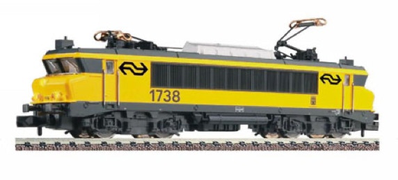
Fleischmann NS 1600/1700
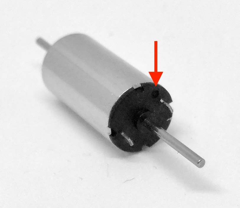
to 12V coreless motor
Fits these version of the Fleischmann 1600 and 1700, as most likely as well SNCF BB 7200, BB 15000 and BB 22200 models;
Among the compatible models of the NS 1600 and 1700 are: art. 7360, 7361, 7362, 7363, 7364. Others might be compatible (with and without flywheel), but I haven’t listed all releases here.
No milling required!
Question? Just reach out!
What you need for conversion set
- The model and upgrade kit
- Small flat screwdriver
- Soldering iron 15W/25W
- Torch
- Gear puller is practical to have
Installation time: Around 45 minutes
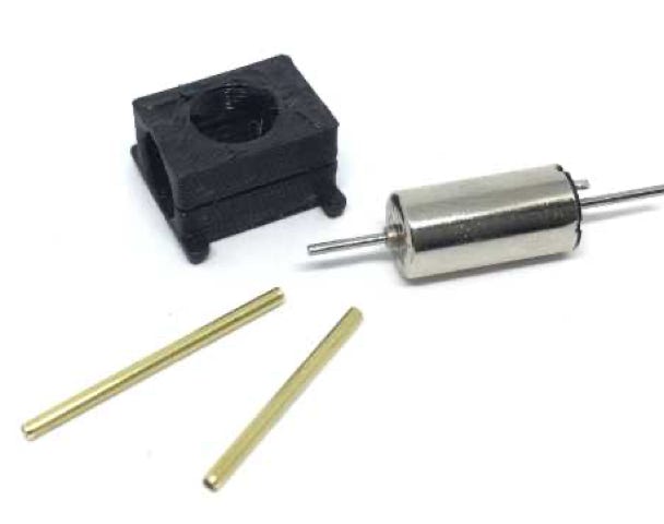
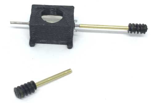
Parts in the kit.

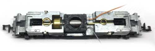
Original frame. Compare this to your model, to make sure you’ve got the right one.
1
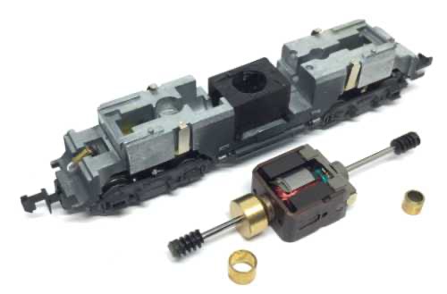
Take the housing off by bending the sides outwards with the nails of your thumb, then pull a bogie towards you to lift the chassis out.
3
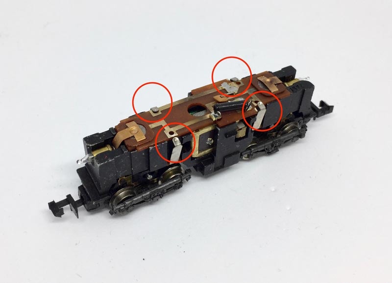
Take the electronics board off and the two brass rings that hold the shafts down out. Put the two light bulbs aside (at the ends of the model), you might loose them.
4
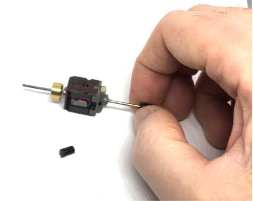
Pull the worms from the original motor. This can be done with your fingers.
5
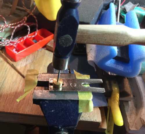
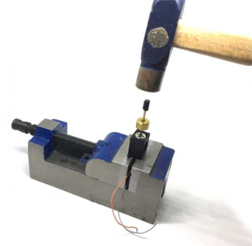
The V slotted plate I’m using here on the picture (right), is part of the Tramfabriek Gear Puller set. You can also saw a slot into an 1mm brass plate or something similar. What you see it the motor on the bottom and the flywheel with axle on the top. HEAT UP the flywheel with the torch for about 6-8 seconds, so the brass softens. Then hammer it straight out. You might want to reheat the flywheel again after 10 seconds. You’ll see and feel after about 3 tries, the flywheel will come off. For the last bit you might want to use the gear puller. I put the one of the 1.75 mm pins of the gear puller in a drill and filed it a bit smaller, so it will push out flywheels like this when it’s under 1.5 mm diameter. More tips on how to remove flywheels, gears and wheels you can read here.
Don’t worry if you bend the V slotted plate, mine has been bent many times, just flatten it again with the hammer.
The next step might be somewhat daunting to some people, but fear not!! Removing and re-fitting the flywheel might seem hard, but it isn’t really. If you have a torch and a medium sized hammer, you’ll be fine. And a gear puller can be handy.
2
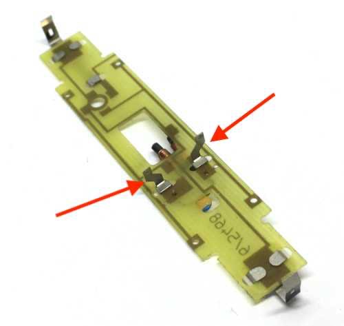
Mind the two lamps on the fronts, put them aside.
Pull contacts sidewards to release PCB board. Take PCB board off.
(image of other model shown here)
6
The flywheel has one side that has a larger diameter. Hammer shortest adapter straight in the flywheel, so it comes out about 1 mm on the other side.

Then press the adapter with flywheel on the motor. You might have to carefully hammer it on the motor, as the flywheel makes the inner diameter of the brass adapter a fraction smaller.
7
Firmly, but carefully press the worm on the brass adapters until the ends are aligned. Do this for both worms. Push the adapters on the motor shaft. ONLY when they spin loose, you need to glue it (a little Loctite), but the tubes I had, had a nice push fit.
8
9
10
Before you solder the wires, check what the plus pole is of the motor. You can see this by the + mark (duh!). The plus pole should be on the left side in the casing, but you can always swap the wires if you have done it the other way around.
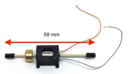
Solder wires to the motor. The Tramfabriek sells the best thin wire you ever will have here, to install electronics in model trains. The orange wire on the picture is (unconventionally) connected to the minus.
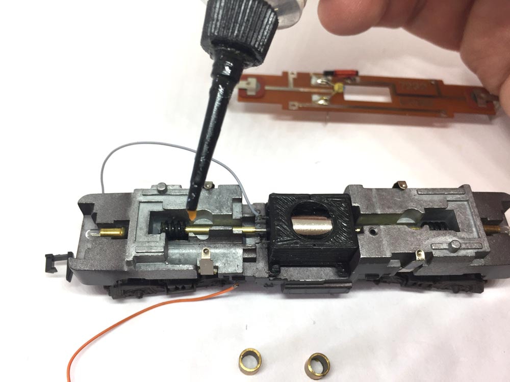
Before you place the brass rings back, put a little oil on the shaft where the ring will press on it.
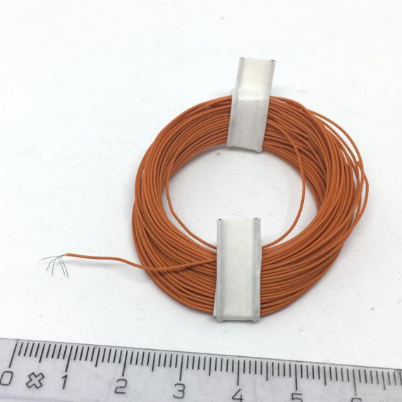
Get the best wire here
11
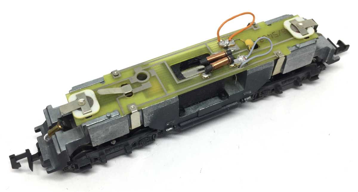
You can remove the contacts that were touching the original motor. But they should not bothering anything if you would leave them there.
You can route the wires from the motor through two holes in the electronics board. Solder these to the solder pads. Test the motor by holding two wires with power on those solder pads. You can only test the model on the track if the housing is back on. Now test that your model is going in the same direction as your other trains and the correct light turns on, otherwise you’ll have to swap the connections to between the motor and the board around.
12
Don’t forget to put the light bulbs back in place!
Digital conversion
This motor upgrade kit can very well be converted to DCC. Check the digital setting page, for many decoders, to get the best driving experience.
And one more model has been brought back to the future!
•