

UK based
Prices for UK customers are shown inc 20% VAT
Other countries, inc EU, prices shown are ex VAT.
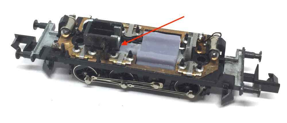
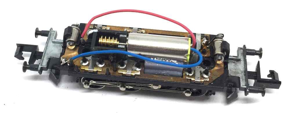
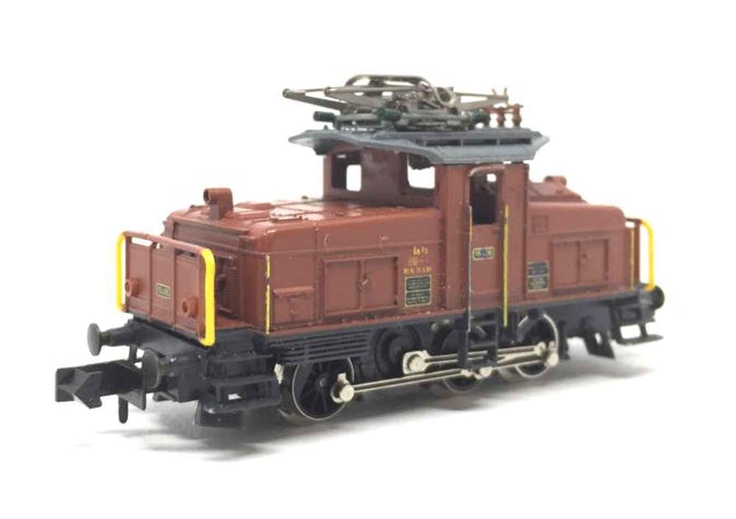
Upgrade Arnold Ee 3/3
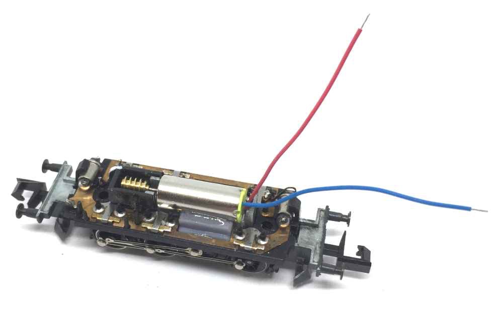
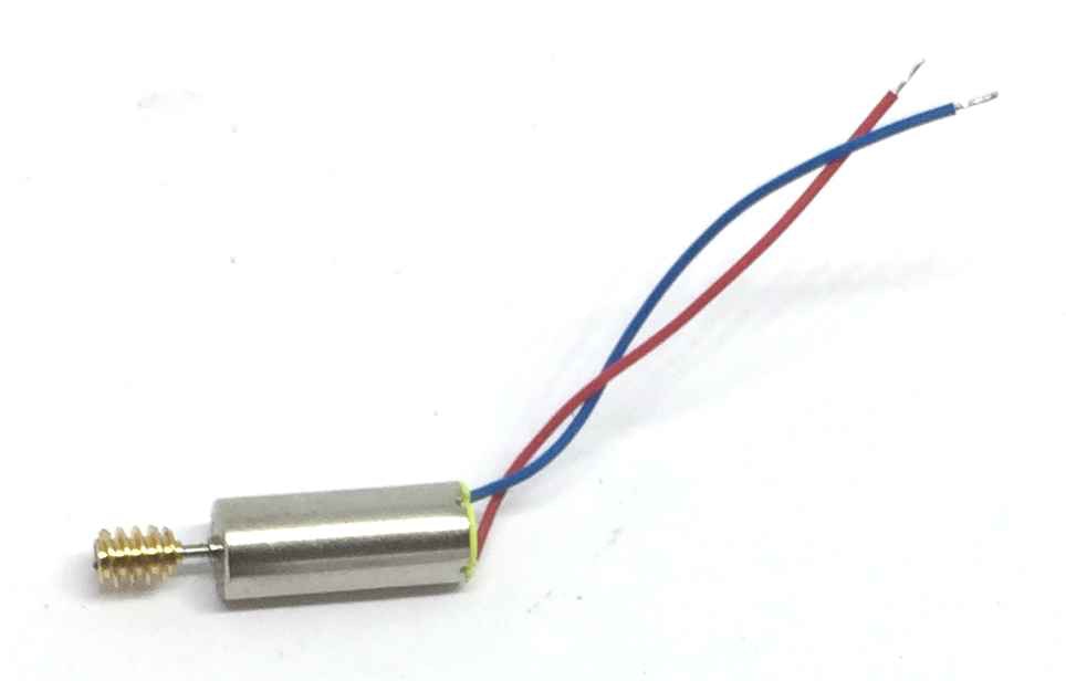
to 12V coreless motor
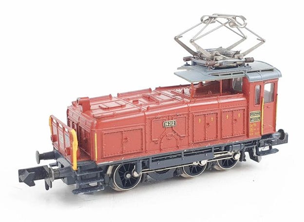
Fits Arnold art. 0104, 0109, 0160, 0161, 0215, 2420, 2421, 2422, 2423, 2424, 2425, 2426, 2427, 2428, 2431, 8620 and similar models (open your model to check compatibility).
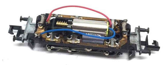
What you need for conversion set
- The model and upgrade kit
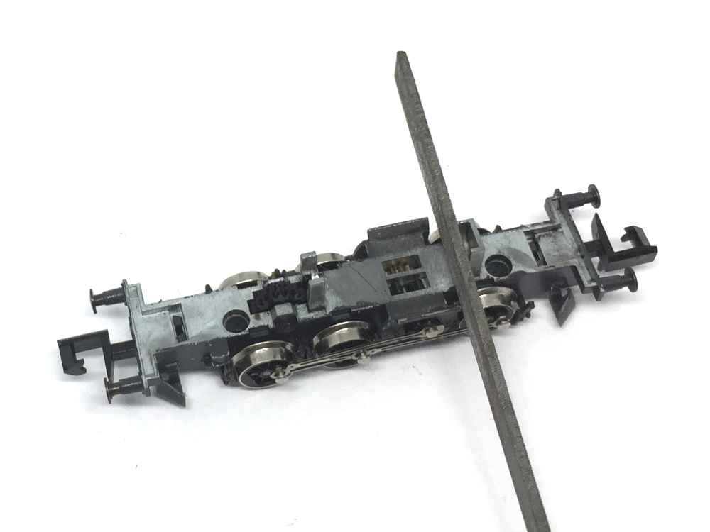
- Small flat screwdriver
- Soldering iron 15W/25W
- A small file
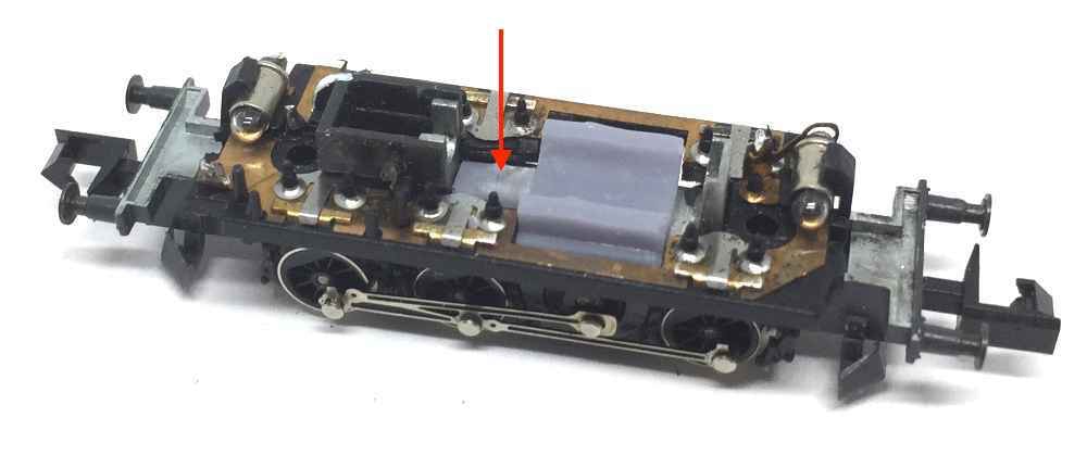
- Epoxy glue
- Generic modelling tools
Installation time: Around 40 minutes
Difficulty: Bit fiddly, but not too hard.
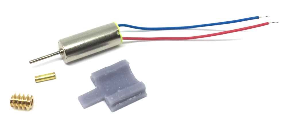
Contents of the kit


Question? Just reach out!